


FITTING A COACH FOR WIRELESS RECEPTION.
Page 28
Page 29
If you've noticed an error in this article please click here to report it so we can fix it.
Further Detals Concerning the Equipment of a Motor Coach so that the Reception of Broadcast Programmes can be Added to the Pleasure of a Party.
IN LAST WEEK'S issue of The CommercialMotor we commenced a short series of articles which . will deal fully with the actual details of equipping a coach for the reception of the programmes broadcasted from the transmitting stations, the idea being that coach proprietors should make the experiment of so equipping one or more vehicles and: thereby gaining experience first upon the extent of the appeal made to the public by the additional source of amusement, and, second; upon the type of apparatus most suitable to the purpose.
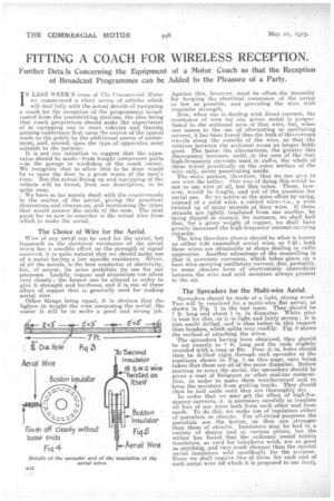
It is not our intention to suggest that the appa• ratus should be made—from bought component parts —in the garage or workshop of the coach owner. We recognize that to allow this to be done would be to open the door to a great waste of the men's time. But the actual fitting up and equipping of tha vehicle will be found, from our description, to be quite easy. . . We have so far merely dealt with the•requirements in the matter of the aerial, giving the practical dimensions and clearances, and mentioning the types that would answer the needs of the ease. The next point for us now to consider is the actual wire from which to make the aerial.
The Choice of Wire for the Aerial.
Wire of any metal can be used for the aerial, but inasmuch as the electrical resistance of the aerial wires has a sensible effect on the strength of signal received, it is quite natural that we should make use of a metal having a low specific resistance. Silver, i of all the metals, s the best conductor of electricity, but, of course, its price prohibits its use for our purposes. Luckily, .copper and aluminium run silver very closely; the former canbe alloyed in order to give it strength and hardness, and it is one of these alloys of copper that is generally used for making aerial wire.
Other things being equal, it is obvious that the lighter in weight the wire composing the aerial, the easier it will be to make a good and strong job. Against this, however, must be offset,the necessity for keeping the electrical resistance of the aerial is low as possible, and providing the wire with requisite strength. Now, when one is dealing with direct current, the resistance of wire for any given metal is proportional to the sectional area of that wire, but, when one comes to the use of alternating or oscillating current, it has been found that the bulk of this current travels along the outside of the wire, so that the relation between the sectional -areas no longer holds good. The faster the alternations, the greater this discrepancy becomes, until, in the case of the very high-frequency currents used in radio, the whole oE these travel practically on the outer surface of the wire only, never penetrating inside.
The more surface, therefore, that we can give to our wire the better. One way of doing this would be not to use wire at all, but thin tubes. These, however, would be fragile, and out of the question for aerial use. So we arrive at. the same effect by using, instead of a solid wire, a cabled wire—i.e., a wire twisted up of many strands of finer wire. If these strands are lightly, insulated from one another, by being dipped in enamel, for instance, we shall find that, for a given weight of copper, we shall have -greatly increased the high-frequency current-carrying capacity. The wire therefore chosen should be what is known as either 3.20 enamelled aerial wire, or 7.22; both these wires are obtainable at shops dealing in radio apparatus. Another advantage of the enamelling is that it prevents corrosion, which takes place on A bare wire carrying oscillatory current, due, probably, to some obscure form of electrostatic electrolysis between the wire and acid moisture always present in the air.
The Spreaders for the Multi-wire Aerial.
Spreaders should be made of a light, strong wood. Two will be. required for a multi-wire flat aerial, as shown in Fig. 3 in the last issue. They should be 7 ft. long and about 1 in. in diameter. -White pins is best for this. as it is light and fairly strong ; it is also easily drilled, and is thus better in this respect than bamboo, which splits very readily. Fig. 3 shows
the method of attaching the wires.
The spreaders having been obtained, they should be cut exactly to 7 ft. long and the ends slightly rounded with a rasp or file. Four holes should then be drilled right through each spreader at. the positions shown in Fig. 3 on this page, care being taken that these are all of the same diameter. Before starting to erect the aerial, the spreaders should be given a coat of Solignum or other coal-tar composition, in order to make them weatherproof and to keep the moisture from getting inside. They should then be laid aside until they are thoroughly dry.
In order that we may get the effect of high-frequency currents, it is necessary carefully to insulate all four of our wires both from each other and from earth. To do this, we make use of insulators either of porcelain or ebonite. For all-round purposes the porcelain are the better, as they are stronger than those of ebonite. Insulators may be had in a variety of shapes and at various prices, but the writer has found that the ordinary round bobbin insulators, as used for telephone work, are as good as anything, and very much cheaper than the special aerial insulators sold specifically for the purpose. Since we shall require two of these for each encl of each aerial wire (of which it is proposed to use four),
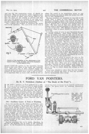
and two for the, supporting wires, 18 should be obtained. They can be had for under sixpence each, but care should he taken when buying them to see that the glaze on the outside is perfect and that they are not chipped or cracked in any way, as in this latter condition they let in moisure, which, very quickly reduces their insulating capabilities. Fig. 4 shows the method of attaching the aerial wire to the insulator. The end of the aerial wire is passed round the groove in the insulator, leaving about 6 ins. over when it has made one complete turn. This free end is then twisted round the original aerial wire about 10 or 15 times, and the end clipped off and. pressed down with a pair of pliers. It is important that no loose ends should be left an eiCher the aerial or its supporting wires, as any points sticking out tend to make the aerial very difficult to tune satisfactorily.
Having attached one insulator to one end of the aerial wire, a piece of wire about 18 ins. long (ordinary 18-gauge copper wire will do for this) is threaded through the hole in the bobbin, as shown in Fig. 5, formed into a stirrup, and twisted back on itself. The free end of this wire should then be passed round a second insulator in the same way as was the aerial wire. The distance between the two insulators, when in place, should be between 4 ins. and 6 ins. .
A further piece of wire is now threaded through the second insulator, after being formed into a stirrup as before, and then (in the case of the two outside wires in the aerial) passed through one of the holes in one end of one spreader, wrapped half round the spreader and passed through the hole a second time, leaving a distance Of about 4. ins, between the last insulator and aerial. The free end is then passed round another bobbin insulator, leaving about 4 ft. s ins, between the spreader and this insulator. Do not cut the wire here, but, after twisting it on itself several times, carry it back to the hole of the other end of the spreader, and, having secured it to the spreader in the same. way-as before, cut the other end off, leaving enough to form the first stirrup for the first insulator op that side. This insulator could be secured in place, ready for attachment by wire to the first insulator of the aerial wire.
Another way in which to secure the wire to the spreader is to pass it through the hole, wrap it once right round the outside of the spreader, and loop it through the wire where it emerges from the farther side of the hole. This acts . as a hinder to the spreader, whereas the first. method only binds one half of the section to the spreader. Each method is shown in Fig. 6, which shows the wiring as here described.
Great care should be taken that the two lengths of wire aee exactly the same, so that the spreader will lie horizontally when slung: