


THE LATEST 5-TON AUTOCAR.
Page 15
Page 16
If you've noticed an error in this article please click here to report it so we can fix it.
An Interesting Type of Chassis, which Embodies an Engine Situated Under the Driver's Seat and with a Ball-bearing Crankshaft, and an ingenious Rotary Tipping Gear.
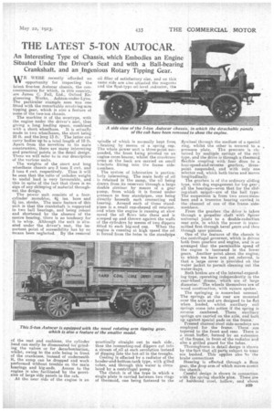
WE WERE recently afforded an opportunity for inspecting the latest five-ton Autocar chassis, the concessionnaires for which, in this country, are James C. Fell, Ltd., Oxford Engineering Works, . Ashton-under-Lyne. The particular example seen was one fitted with the remarkable revolving-arm tipping gear, which is also a feature of some of the two-ton chassis.
The machine is of the overtype, with the engine under the driver's seat, thus giving a long loading space, combined with a short wheelbase. It is actually made in two wheelbases, the short being 10 ft. and the long 13 ft. The latter can carry bodies up to a total length of 18 ft. Apart from the novelties in its main construction, there are many interesting and practical points in the detail design. These we will refer to in our description of the various units.
The weights of the snort and long wheelbase chassis are 3 tons 2 cwt. and 3 tons 4 ewt. respectively. Thus it will be seen that the ratio of unladen weight to useful load is very favourable, and this in spite of the fact that there is no sign of any skimping of material throughout the design.
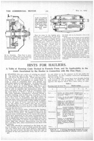
The power unit, consists of a four. cylinder monobloc, 44 ins, bore and 51 ins. stroke, Thu main feature of this unit is that the crankshaft is supported in two ball bearings, and being robust and shortened by the absence of the centre bearing, there is no tendency for it to whip. .Although the unit is situated under the driver's seat, the important point of accessibility has by no means been neglected. By the removal of the seat and cushions, the cylinder bead can easily he dismounted for grinding the valves or for decarbonization, whilst, owing to the axle being in front of the crankcase, instead of underneath it, the sump can be dropped and work performed without trouble on the main bearings and big-ends. Access to the engine is also facilitated by the provision of large side panels in the cab. At the near side of the engine is an oil filler of satisfactory size, and on this same .side are also situated the magneto and the float-type nil-level indicator, the spindle of which is normally kept from
ibr a ti n g by means of a spring cap. The whole power unit is three-point suspended, the front being pivoted on an engine cross-bearer, whilst the crankcase arms at the back are carried on small brackets fitting into the frame sidemembers,
The system of lubrication is particularly interesting. The main body of. oil is retained in the sump, the oil being drawn from its reservoir through a large double strainer by means of a gear pump, from which it is forced under pressure to four standpipes, one being directly beneath each connecting rod bearing, Around each of these standpipes is a small cup-shaped oil retainer, and when the engine is running at slow speed the oil flows into these and is scooped up and thrown against the walls of the cylinders by means of two dippers fitted to each big-end cap. When the engine is running at high speed the oil is forced from the holes in the standpipe practically etraight out to each side, thus the connecting-rod dippers cut into a stream of at each revolution instead of dipping into the hot oil in the troughs. Cooling is effected by a radiator 0 the header-and-bottom-tank type, with gilled tubes, and through this water is circulated by a centrifugal pump. The clutch is of the type in which a single plate is carried betVeen two rings of thermoid, one being fastened to the flywheel through the medium of a special ring, whilst the other is secured to a
pressure plate. The pressure is obtained by multiple springs of the coil type, and the drive is through a thermoid flexible coupling with four discs to a four-speed-and,reverse gearbox, threepoint suspended, and -with only one selector rod, which both turns and moves longitudinally. The gearbox is of the ordinary sliding type, with dog engagement for top gear ; all the bearings—even that for the slidL jug-shaft spigot—are of the ball type. The suspension is from two cross-mern, bers and a trunnion bearing carried in the channel of one of the framesidemembers.
From the gearbox the drive is taken through a propeller shaft with Spicer universal joints to a double-reduction near axle, in which the power is transmitted first through bevel gears and then through spur pinions.
One of the features of the chassis is the centrifugal governor, which is driven. both from gearbox and engine, and is so arranged that the permissible speed of the engine is increased in the lower gears. Another point about the engine, to which we have not yet referred, is that a large cover is provided on the water jacket to permit cleaning out the water-ways. Both brakes are of the internal-expanding type, operating independently in the rear-wheel drums, which are of large diameter. The wheels themselves are of wood construction,with square spokes.
The springing is .somewhat unusual. The springs, at the rear are mounted over the axle and are designed to be flat when loaded, whilst auxiliary, coil springs come into action if the spring is reverse cambered. These auxiliary springs are carried on the axle, and butt up against special pads on the frame: Pressed channel-steel side-members are employed for the frame. These .are tapered to the front and rear. There is a. stout buffer, formed by an extension of the frame, in front of the radiator 'and also a grilled guard for the tubes. Thoroughness in detail design is shown by the-fact that all parts subject to Wear are bushed. This applies also to the brake connections Steering is effected through a Ross gear, the drop arm of which moves acrosi the chassis: Careful design is shown in connection with the 'spring shackle pins: These are of haidelied steel, hollow, and. about B29
a ins. -diameter. They float in phosphor-bronze bushes both in the shaekles and spring eyes, and are kept filled with lubricant by means of a grease gun. Now we come to the tipping gear. With this it is impossible for the body to be overwound or to drop down accrdentally. Tho power is taken off the primary shaft of the gearbox by means of a sliding gear. There is a small reduction at this point, and the drive is then taken through a Carden shaft to worm gearing, after which there is a further reduction by spur gearing, which drives a cross shaft carrying the rotating arms the movement from these being carried to the body by connecting rods. The bushes of the connecting-rod fulcrum pins are oval, whilst the pins themselves are round. This gives a free swing of approximately 10 ckgrees at the bottom, so that the driver does not have to exercise extreme accuracy in order to let
the body rest on its brackets when it is ' lowered.
At the back of the body are two special hooks holding the tailboard, and as the, body tips the ends of these hooks bear
on a cross-member of the chassis and release the tailboard. This saves re moving the pins by hand in order to
shobt the load. The strain of the dip is spread over the main frame by carrying
all the driving gear, with the exception of the take-off, on a sub-frame,The upper or moving frame of the tipping gear forms a substantial body support-. It is pivoted at the rear and is built up Of angle-steel longitudinal members.
The standard contractor's body is steel lined and has detachable steel sides and tailboard.