


A NEW DESIGN OF TRACTOR-LORRY.
Page 11
Page 12
If you've noticed an error in this article please click here to report it so we can fix it.
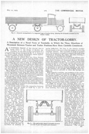
A Description of a Novel Form of Turntable, in Which the Three Directions of Movement Between Tractor and Trailer Positions Have Been Carefully Considered.
AS FURTHER PROOF of the interest that is being taken in the design of flexible sixwheelers, we are able to give particulars of a very promising device invented by Mr. T. A. Jones (of 79, Weston Road, &rood, Rochester), whose application for a patent has been accepted. With this type of vehicle there are three distinct movements between the tractor and the trailer which have to be considered. First, a ,swivelling movement when turning corners ; second, a vertical hinge movetnent when any axle rises or falls, or springs deflect; third, a side-tipping movement when any single wheel rides over an obstruction or falls into a depression. The second and third movements must be allowed for, not only when the tractor and trailer are in a direct line _,e but also when they are at an angle when turning.
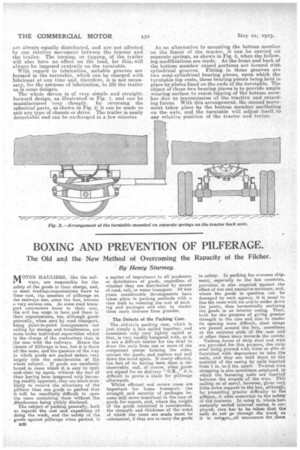
Many flexible six-wheeler designs allow only for the second movement freely when the tractor and trailer are in a direct line ; and the third movement is usually left to be counteracted by the variation in deflection of the springs, or the flexibility of the frames. Another point which requires careful consideration is the transmission of the tractive and ietarding forces between the tractor and the trailer ; there must be no danger of a breakaway between the two parts. "Again, sufficient stability is required to prevent undue rolling or overturning of the trailer. In•the design under review the connection between the tractor and the trailer is made by a pair of spherically shaped members working one within the other. The top mem ber, which is attached to the trailer, is fitted with a spigot, which , projects through a circular hole in the bottom member at tached to the tractor frame. Fitting on the underside of the bottom member and attached to . the spigot is a spherically shaped washer, which holds the two portions together. This washer is free to revolve on the spigot, and is connected to the bottom member by four helical springs. The rims of the two portions are so proportioned, that enough clearance is left to allow either of them to tip in any direction ; sufficient to allow for any inequalities of roadway or spring deflection, the hole in the bottom member being of such a size as to allow the spigot to move the requisite amount. The turntable is made of pressed steel, the necessary strength to support the load being obtained by flanging the edges, and thus forming a cross-girder of considerable strength. The rear of the trailer is carried on an ordinary twowheeled axle, which thus gives three-point suspension, and allows freedom of movement in any direction within the prescribed limits. It is quite evidtait that it does not matter whether the tractor and trailer are directly in line or at an angle, the three movements, previously described, are freely allowed. Therefore, no distortion or uneven stress is placed on any part of the frames or the springs, when turning, when running over uneven ground, or when the springs are deflected.
With regard to stability, any tendency of the trailer to roll will be damped out by the springs attached to the bottom washer, and there is no danger of overturning so long as the centre of gravity of the trailer remains inside the triangle formed by the points of support.. In other words, the suspension is similar to that of the overtype steam wagon with traction engine steering, except that there is less tendency to roll. It might be thought • that, because there may be nearly as much weight at the front of the trailer, as at the back, three-point suspension does not give sufficient stability, but when it is considered that, for years, traction engines with similar suspension have been constructed with jib cranes in front, and where the weight on the front axle, when loaded, exceeds the weight on the back axle, it is quite evident that such is. not the case. Consideration of the design will also show that " the. trailer could not overbalance, because, after a certain tipping angle is reached, which is long before the centre of gravity of the trailer could move out of the triangle of support; the, halves of the turntable would be locked.
With regard to the tractive and retarding forces, these are transmittede
through the turntable In a very direct manner; and there is no possibility of a breakaway. The stresses
are always equally distributed, and are not affected by any relative movement between the tractor and the trailer. The turning, or tipping, of the trailer will also have no effect on the load, for this will always be imposed centrally on the turntable.
With regard to lubrication, suitable grooves are formed in the turntable, which can be charged with lubricant at any time and, therefore, it is not necessary, for the purpose of lubrication, to lift the trailer as in some designs.
The whole device is of very, simple and straight, forward design, as illustrated. in Fig. 1, and can be manufactured. very cheaply, by reversing the spherical parts, as shown in Fig. 2; it can be made to suit any type of chassis or drive. The trailer is easily detachable and can be exchanged in a few minutes As an alternative to mounting the bottom member on the frame of the tractor, it can be carried on separate springs, as shown in Fig. 3, when the following modifications are made. At the front and back of the bottom member raised portions are formed with cylindrical grooves. Fitting in those grooves are two semi-cylindrical bearing pieces, upon which the turntable top rests, these bearing pieces being held in place by plates fixed on the ends of the turntable. The object of these two bearing pieces is to provide ample wearing surface to resist tipping of the bottom member due to transmission of the tractive and retarth ing forces. With this arrangement, the second movement takes place by the bottom member oscillating on the axle, and the turntable will adjust itself, to any relative position of the .tractor and trailer.