


WEAR AND TEAR ON STEAM VEHICLES.
Page 12
Page 14
Page 15
If you've noticed an error in this article please click here to report it so we can fix it.
The Foden—Dealing With Worn Points and Providing Against Neglect, and Results of Unfair. Treatment and Against Damage.
Al"T ARTICLE appeared recently in The Commercial Motor entitled " Steam Haulage on the Western. Front," giving a general outline oi tile types of steam vehicles employed behind the lines .and the uses to which they were put. In that article .a few defects which developed owing to abnormal road conditions were deal with. The writer now proposes to take each make separately and to. make a rough analysis of the design, giving the method of repairs adopted at the .0 ront whenever faults developed, with the view of assisting makers, owners and crews of the various machines.
It may be stated at once that a number of the defects which develoird were common to all makes, this .being especially so in the case of the overtype steam wagon.
Let us begin with the Foden steam wagon, as this make was present in greater numbers than any other in France.
This machine, manufactured by Fodens, Ltd., of Sandbach, is fitted with loco-type boiler, with overtype compound slide valve engine with Stephenson link motion. It is chain-driven with two speeds and compensating gear on the rear axle. The working pressure of the boiler is 200 lbs. per sq. inch. A feed pump and injector are provided, and there are two brakes, one worked by foot on the rim of the flywheel and one worked by hand On a drum carried on the rear axle. A three-way cock working in conjunction with the regulator provides, in case of tl. short heavy pull, a means of admitting high pressure steam, to both H.P. and L.P. cylinders, commonly known' as double high pressure. In the a-ton wagon, the cylinders are 31 ins: and Q ins. by 6 ins. stroke ; in the•5-ton, 4 ins. and 6i ins. by 7 ins. stroke. In. each case the cranks are counterbalanced, and the boiler is designed with ample heating surface to giveeasy steaming under all conditions. Ample 'space for carrying fuel and water is provided. The frame is of channel section and, on anything like passable roads, should be well up to its work, although it gave trouble under the abnormal conditions up the line as will be explained later on. The boiler is rigidly held in the frame at the smoke-box end, expansion being taken up by the attachment on each side of the firebox.
Where Wear First Occurs.
In analysing such defects as were found, it will be as well to deal with them in the following order :(1) Rear axle ; (2) front axle ; (3) frame ; (4) steering; (5) boiler ; (6) engine; (7) gearing and chain; (8) body (including tipping gear).
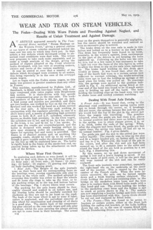
1. Rear Axle.—The flanges of the axle journals wear on their faces and the corresponding faces on the bearings wear, causing considerable side play to develop in the whole axle. The method adopted to overcome this trouble was either to draw the wheels and fit loose slip rings to take up the wear, or to pin packing strips on to the top and bottom halves of the bearings. Fig. 1 shows where wear occurs.
The packing for the axle boxes should be thoroughly cleaned and soaked in oil before use, and the bearing bolts should be carefully watched for slackness as they• are apt to jar loose on the road. i The bush of the loose wheel s apt to wear if lubrication is neglected, and the periodical removal of this wheel for examination and cleaning of oil ducts is a good plan. The centre bush of the compensating gear carried on the rear axle wears and side play develops, whilst the pins carrying the planet pinions are apt to come loose in their housings. The actual wear on the gears themselves is generally negligible, but the centre should be watched and rehtted as soon as excessive play is noticed.
The brake drum on the rear axle is made in two halves and bolted on to a feather in the back axle. This drum has frequently been found to be loose, generally, in the writer's opinion, from carelessness on the part of the drivers in not keeping the bolts tightened up. Following up the bolts was the cure for this, but in a few cases it was necessary to take a light cut over the faces of the two halves in order to allow the drum to nip on.the axle when tightened up. The brake band working on this drum gave trouble at times. It was found that, after the linings of the bands had worn to a certain extent (not surficie„nt to warrant relining), the Prake-actuating links were apt to foul the holding-up springs of the band when the brake was pulled on.. To overcome this, the springs were moved to the position indicated in Fig. 2. An additional spring fitted at the rear end of the band was found to be-of much assistance in holding up and off the band. The bolts holding the locating clips on the band were very apt to shake loose and needed constant watching.
Dealing With Front Axle Details.
2. Front Axle.—It was found that, owing to the abnormal road conditions, front spring leaves were apt to break through the centre, or, if breakage did not occur, the springs became flat and the guide pin would foul the top "of the slot in the swivel jaw when the wagon was travelling. The practice adopted, when the guide pin had risen in. above its normal position and there were no broken leaves in the spring, was to place slipper pieces, -a in. or 1 in. thick, under the ends of the spring. When, after the slippers had been 'fitted, the guide pin had again risen, the spring was taken offand set up to its normal camber. Fig. 3 gives details.
The guide pin and the slot in the swivel jaw wore rather rapidly. The remedy was, to true up the slot and fit a larger headed-pin, or, better still, to drill and tap to 1 in. Whitworth, the head of the pin in , the centre, and after the slot and pin had been squared up, to fit a suitable liner to the sides and round the head of the pin held in position by a set bolt, Fig. 4 illustrating this.
By this means., no up and down movement of spring is lost and a heavy forging is saved. If the liner be made of mild steel, it will be the 'partthat will wear instead of the slot and can be easily replaced. .
The front axle journals wear somewhat, especially the right-hand one on the underside at the inner end of the journal. This is caused by the heavy camber of the French roads. When the wear becomes excessive, the axle can be turned upside down and a fresh bearing surface obtained. The rivets holding the swivel-jaw-retaining-plate to the bridge on the smokebox come loose and the best plan, is to replace them with fitted bolts made with a thin head and nut. The rivets holding the bridge to the smokebox come loose and the bridge is apt to crack at points shown in Fig. 5. The makers are now supplying a heairier bridge and, little trouble has been experienced with this. Loose rivets should -be cut out and replaced by fitted bolts.
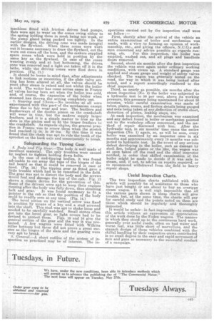
3. The Frame.—This was found to be prone to fracture at certain points, either at the front bolt holding the radius rod bracket, at the bolts holding down the cab, or, in the case of wagons fitted withThresh Disinfecting Drums, at the front bolt holding (lown cradle of the bout drums. The fracture, almost invariably started with a hair crack on t'ne outside edge of the channel flange, spreading through the bolt hole, and, if the frame was 'not patched, ultimately resulting in complete fracture. Th.3 method -of patching was ,to fit a long flat paten 5 ft. 6 ins. by 6 ins. by in. or if in. into the wab of the channel, chamfering the top-and bottom edges of the patch to
suit the fillet of the channel, fhe patch being held in position as far is possible by bolts passing • ,:hrough the existing rivet' holes and, where these were not avail able, by in. bolts, the holes for same being drilled on the centre line of the web. It is essential that tho patch should be made a snug.(pre ferably driving) fit
between the top Fig. 17.—Inspection chart and the bottom
•
/9;7worn
No clearano avot (rarely) mt.
(Spring slat
Run rock Wheels. require odiasPnern:
Clearance not robe /en moo! Block worn
Pin worn
flanges and at the same time be well bedded into the web, as shown in Fig, 6.
There were alternative plans for patching, but the one described was generally adopted as combining' reliability with ease of obtaining the necessary material and fitting. The writer knows of no case of a frame giving further trouble after this patch had been properly fitted. The earlier Fodens had their radius rod brackets bolted direct to the frame' but in the later built ones the radius rod bracket was bolted to another bracket which was in turn bolted to the frame, as seen in Fig. 7. This ippearecl to stop frame breakages at this point to a large extent.
The most recent wagons sent to France were fitted with duplex radius rods, as indicated in detail in. Fig. 8.
4. Steering.—This gave very little trouble and is highly reliable even on very rough roads. The only improvement that the writer can suggest would be to bush the two steering brackets to allow of renewal. in case of wear and to leave the chain barrel shaft
slightly smaller (say, in.), where the worm wheel is keyed on, than the journal at that end. The reason for this is that the journal and bracket wear in the course of time and any bush that may be fitted must be large enough to pass over the unworn part of the shaft on which the worm wheel is keyed, and will thus ,be a slack fit on the journal. (Fig. 9.)
5. Boiler.—This is excellently designed and well
up to its work and very little trouble was experienced. The most common troubles were occasional leaking stud stays and leakage at the
rear vertical seams, where the horn plates carry. ing.the crankshaft spring from the boiler, and slight leakage at the steering brackets, all readily cured by light use of the caulking tool. The writer knows of no case of failure of this boiler except on the part of the
The boilers were inspected frequently and thoroughly, and the Ranasbottom safety valves were all ferruled to prevent the drivers tampering with them or attempting to work the boiler at a higher pressure than is allowed by the makers Fig. 10 shows the method of ferruling. The asbestos packed cocks on the water gauge Were prone to leak and suitable packing was hard to obtain. The injector steam valve also gave some trouble by leaking. Boiler tubes were generally drawn after 3 to 3•i years' use for cleaning purposes.
6. Engine.—This is an excellent piece of mechanism, and gave practically no trouble at all, except that which was due to fair wear and tear. It was found to be of advantage to fit liners to the big-end brasses to bring the two halves metal to metal, as, in Summer, on dusty roads, considerable grit found its way into the bearing if left open, and scoring of the crankpins and brasses resulted. In the case of
machines fitted with friction driven feed pumps, flats were apt to wear on the cones owing either to the spring holding them in mesh being too weak, or the pump gland being packed too tightly. In the earlier designs, the driving cone was made integral with the flywheel. When these cones were worn out it became necessary to draw the flywheel, cut the worn out cones off the boss, and the makers supplied spare cones which were held in position by the same key as the flywheel. In case of the cones wearing evenly and at last bottoming, the driven cone was removed and a light cut taken off it in the lathe, while the driving cones were filed down in position. (Fig. 11.) • It should be borne in mind that, after adjustments to link motions or eccentrics, if the slide valve setting has been altered at all, the valves should be reset after steam is raised and not whilst the boiler is cold. The writer has come across cases in France of valves having been set when the boiler, was cold, and, of course, the expansion of *the boiler when steamed has thrown the setting completely out.
7. Gearing and Chain.—No troubles at all were experienced with this part of the mechanism except those due to fair wear and tear. The feathers and featherways of the double pinion on the crankshaft will wear in time, but the makers supply larger feathers' and it is a simple matter to true up the slots in the pinion and to fit the larger feathers to . the crankshaft. As regards chins, the general practice in France was to renew them when the stretch had reached l in. in 30 ins. By this time it was found that the chain was apt to ride the teeth of the sprocket on the back axle and consequently to break.
Safeguarding the Tipping Gear.
8. Body and Tip Gear.—The body is well•made of excellent material. The only troubles were caused by neglect to tighten holding down bolts.
In the case of end-tipping bodies, A was found advisable to cut away the tops of the hinges of the tail board so that it could be removed in case of need. (Fig. 12.) The tipping gear as fitted gave a little trouble which had to be remedied in the field. The gear was apt to distort the body and the screws would foul and damage the top of the cab. Fig. 13 shows a simple device for the prevention of this. Some of the drivers were apt to keep their engines running after the body was fully down, thus straining belt and gear. It was found necessary to fit a Pointer in the cab so that the position of the body could be readily seen at any time. (Fig. 14.) The bevel pinion on the vertical screw was fixed in position by means of a key and a stud screwed into the shaft. This stud was apt to shake loose and needed to be carefully watched. Small stones often got into the ,bevel gear, so light covers had to be devised to protect them. Figs. 15 and 16 give the general outline of the gear and the way it was protected. A few . wagons were fitted with Wilkins feller bottoms but these did not prove a great success as the hinges of the slats and the gearing were very apt to break.
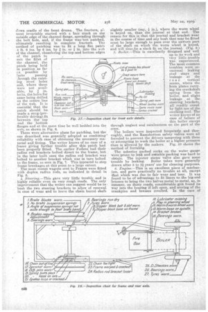
' 9. General.—A short outline of the system of inspection as practised may be of interest. The in
spections carried out by the inspection staff were as follow :— • First, shortly after the arrival of the vehicle an entire examination of boiler and mechanism was made, with a view to forming an opinion of workmanship, etc., and giving the officers, N.O.O.s and men concerned any advice possible as regards run ning, etc. For this inspection, the boiler was emptied, washed out, and all plugs and handhole doors removed. Second, about six months after the first inspection the vehicle was seen again under ordinary working conditions, with steam up. A standard gauge was applied and steam gauge and weight of safety valves checked. The wagon was generally tested on the road, the way in which it was being looked after noted., and a report accordingly rendered to the chief inspector. Third, as nearly as possible, six months after the steam inspection (No. 2) the boiler was subjected to a hydraulic test to 50 per cent. above its working pressure, this pressure being maintained for about 30 minutes, while careful examination was made of tubes, plates, seams, and firebox details being gauged and note being taken of anyfieflection of crown sheet, distortion of plates, leaking stays, etc.
At each inspection, the mechanism was examined and any defect foundin boiler or mechanism pointed out to the workshop officer concerned, and the method of repair discussed with him. After the hydraulic test, in six months' time came the entire inspection (No. 1) again, so, as will be seen, every boiler was examined by an inspector once in six months and approximately every 18 months was subjected to hydraulic test. In the event of any serious defect developing in the boiler, such as damage by shell fire, bulgedplates or the like, the wagon was at once taken off the road and the chief inspector notified, in order that skilled examination of the boiler might be made to decide if it was safe to steam, and, if not, to advise on repairs required, or to recommend withdrawal from the field to heavy
repair shops. s
Useful Inspection Charts.
The two inspection charts published with. this article will possibly be of assistance to those who have just bought or are about to buy an overtype steam wagon. It is Well nigh impossible that all the various parts shown in these charts will give trouble, but, at the same time, the charts will pay for careful study and the points noted on them are those which should be regularly and thoroughly inspected.
It would be unfair—in fact impossible—to conclude this article ',.vithout an expressiou of anpreciation of the work done by the Foden wagons. The manner in which they stood up to the continuous hard work, generally over awful roads, often on bad water and worse fuel, was little short of marvellous, and the staunch design of these vehicles combined with the skilful handling by their respective crews contributed in no small degree to the easy and rapid movement of men and guns so necessary to the successful conduct of a campaign.