


A Powered Steering Gear
Page 62
If you've noticed an error in this article please click here to report it so we can fix it.
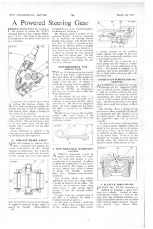
DOWER-ASSISTANCE for steering is I the subject of patent No. 767,075 (General Motors Corp., Detroit, Michigan, U.S.A.). The basis of the patent is the layout of the parts rather than in new principles.
• .A ball-nut (I) is moved up or down by turning the. steering. column (2), There is a little end-play provided in the column and this is used to operate the fluid control valve, Which• is housed in the casing (3), by reaCtion: The novel feature is the use of two separate rocker shafts, one for each side , of the vehicle.. The nut first turns a gear (4) on one rocker shaft, and this gear , meshes with a second (5) on the other rocker shaft, Power assistance is applied to the latter gear by a rack (6) which is moved by the hydraulic servo-Piston 7.
AN EXHAUST BRAKE VALVE
NOW that braking by exhaust throttling is growing more popular, the actual construction of the throttle becomes of importance. It is a heavily loaded component, and must be mechanically strong and even when heated must not be likely to jam in its housing. A suggested practical design comes in patent No. 764,946. (Zahnradfabrik A36
Friedrichshafen A.G., Friedrichshafenam-Bodensee, Germany.) The drawing shows a section of the proposed throttle. A pair of trunnions (I) is mounted on bearing, bushes housed in the casing. The throttle itself is a disc (2) which is notched at two diametrically opposite points to engage in slots in the trunnions, as shown at 3. The obstructive effect of the trunnions is offset by making the valve housing larger than the exhaust pipe. The disc can be removed for renewal by withdrawing spigot 4 and sliding the disc out of its notches.
• REINFORCEMENT FOR SPRING EYES
THE eye of a laminated spring usually has to grip either a metal bush Or the metal sleeve of a rubber bush; this -calls for an interference fit which can unduly stress the eye. A scheme in which the gripping force is supplied by a separate member is disclosed . in patent No. 767504. (I. Brockhouse and Co.-, Ltd., Victoria Works, Hill Top, West Bromwich.) In this schenie the eye itself (1) is made to be a slide fit on the bush. After assembly, a spring-steel clip (2) is placed over the eye. One -end of the Clip paSses under the usual saddle-clip'. (3) whilst the other is secured by an additional one (4).
Should the eye fracture, .the assembly cannot conic apart • owing to the presence of an upturned liP• (5-) 06.04 enclosing member.
A SELF-ADJUSTING SUSPENSION SYSTEM A SPRING suspension cannot' be r-k equally effective under all conditions of load and usually a compromise has to be accepted. A scheme in which the amplitude of frame movement is used as the trigger to bring an extra spring into action is shown in patent No. 767,006. (DaimlerBenz A.G., Stuttgart-Unterturkheim, Germany.)
The drawing shows the scheme applied to one axle; on a large vehicle it would be fitted to all the axles. The axle can, on its separate arms, swing about pivots I, and carries helical springs (2) for the normal resilient members.
Crossing from one swinging link to the other is a stabilizer (3) which is cranked upward at point 4.
At this point is located a hydraulic ram (5) which, when extended, presses on the cranked portion. This applies
a turning moment to the stabilizer which opposes the weight. of the load, and in effect, converts the stabilizer into a pre-loaded torsion bar.
The hydraulic ram is powered by a small pump unit (6) which is .reeiprocated by the vertical deflections ofthe frame. The pump is designed to be operative only in its shortened state so that at light loads it does not affect the hydraulic ram.
COMBUSTION SCHEME FOR OIL • ENGINES
A CCORDINQ to patent No. 767,145 (Ricardo and .Co. Engineers (1927), Ltd., 21 Suffolk Street, London..S.W.1), a rapid air sWirling action in the COrnbusticin chamber may assist the air-fuel intermixture, but such 'engines do not start So. readily as those of the.non-swirl type; The Patent describes a fuel spray which gives good intermixture without swirl,
The. drawing shows a piston at top
dead centre hen practicallyall the air is compressed into the chamber (-1) in the piston crown. The injector 2-is of
the single-hole type and . situated centrally.
The aim of the patent is the provision
of. a conical-tipped deflector plug (3) which is carried centrally in the piston and serves to break up the fuel jet into art umbrella of fine 'spray, as indicated by the dotted lines. If the air in the chamber be rotating, as may unintentionally occur, the coned tip may be fluted to create radial streams of fuel.
A PLASTICS BODY-FRAME DATENT No. 767,248 describes a I method of building a glass fibre
body on a vehicle. Instead of using conventional framing as a base for the glass fibre, the structural membgrs are made from hollow plastics and are filled with a foamed plastic material. (Goodyear Aircraft Corp., Akron. Ohio, U.S.A.)