


A NEW TIPPING GEAR.
Page 32
If you've noticed an error in this article please click here to report it so we can fix it.
A Resume of Recently Published Patents.
Tipping gears for heavy vehicles may be divideu broadly into two classes, hand-operated and power-driven, in connection with the 'former, the attention of designers has been mainly directed towards reduction of the necessary effort requiredto cause the wagon to tip and to bring it hack to its normal position on the chassis. Generally, the methods adopted take the form of so arranging the relation between the centre of gravity of the loaded and unloaded wagon and the pin about which it is hinged that as soon as the operation of tipping is commenced the weight of the load and the body assists in theoperation of tipping, and also when the wagon is empty the weight still aids the operator in returning it, to its normal position on the chassis.
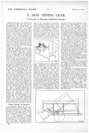
According to patent specification No. 158303, by Peter Brotherhood, Ltd., the folloWing difficulties arise. In cases where the body is mounted so that its centre of gravity when full is behind thepivot about which it is tipped the amount by which ■ the centre of :gravity descends, and therefore the 'impetus which it gives to the tipping body, increases as the operation proceeds. Further, if the body be so constructed that when empty its weight assists to restore it to its horizontal, position this restoring effect also increases as the body approaches the normal. The result .is that in both cases the effect of the weight of the body is at a maximum when it is brought to rest, thus tending to cause
shock. The construction which is described in this specification has been devised with a view mainly to eliminating this defect, so that on licth theupping and restoring motions the centre of gravity moves in a direction which is entirely downward; this motion decreases toward the end of either operation and thus reduces the tendency to cause shock. This essential object is attained by allowing the pivot upon which the body tips to rest upon a curved rail which is mounted upon the chassis of the vehicle. At the beginning of the tip, when the greatest actual effort is generally required, this pivot is near the front of the body and the effect of gravity is at a maximum. As the tip proceeds the pivot approaches the rear of the body and the tendency to tip automatically is correspondingly diminished. On the return movement, owing to the difference between the positions of the centre of gravity of the loaded vehicle and the empty body, the same characteristic phenomenon results.
Other Patents of Interest.
An automatic starter of the compressed air-type is described by G.' Gartmann in specification No. 137813. The invention.has mainly to do with the arrangement of 'valve gear which controls the ingress of the compressed air to the
various cylinders of the engine. The whole of the mechanism is contained within a small cylindrical box leading from which there are a number -of pipes corresponding to the number of cylinders of the engine. These pipes at their inner ends would be in. communiCation with a reservoir • for compressed air ex B28 cept for the intervention of plungers. These plungers noimally cover the inner. end of the pipes and are kept in that position.by.means og light springs. Each is mounted on a spindle which projects at both ends of the plunger. When the plunger is in its normal position covering the outlet to the pipe, one end of the spindle is in contact with the.cover of the main cylinder. This ensures that the compressed air has access to the end of the plunger. The other end is in coiltact with a cam which may be driven
from the engine ,gear by any suitable mean. When there is no compressed air being supplied to the; apparatus the plungers are . subject only to the influence of the light springs which are mounted behind them. These keep them, with the forWard ends of their spindles up against the cover -of the cyN der and sever communication between the delivery pipes and the main chamber. When compressed air is admitted, however, it bears upon the outer faces of the plungers and where the contour of the cam permits pushes them back against the resistance of their springs. The can is so shaped that at any instant those plungers may be pushed back which are blocking up the pipes leading to the cylinders wherein compressed air would be of advantage in turning tile engine. Compressed air is supplied from a main
reservoir or tank, and is admitted to the apparatus by the opening of a small valve conveniently accessible to the driver of the -car or aeroplane. Preferably the valve would be opened by pressure upon a button. The engine would then commence to turn, and as soon as it started to revolve under its own power, the button would be released, the supply of compressed air to the apparatus would be cut off, and the plungers would then ; all he subject only to control of the springs. They would not be continually in motion against the face of' the cam.
M. S. Napier provides against " piston -slap " occurring in connection with aluminium pistons working in cast-iron or steel cylinders by slitting the skirt of the piston and fitting inside it a ring of the same material as the cylinder, of such a size that only the same clearance is left between the outside of the piston and the bore of the cylinder as would be the ease if both materials were the same. The specification is numbered 158525.
An electrically operated safety device whereby the Magneto current is earthed when the engine lubrication pressure falls is described in specification No. 146229, by B. Beraldi
In the exhaust silencer which is described by G. Nicholls in. specification No. 158444, the exhaust gases traverse the length of the silencer five times before emerging into a -bonical box which has a wide exit. r.
C. Fredriksen fits a chassis with three pairs of springs. Considering those on One side only, there is a central semielliptic spring bolted at its centre to a bracket fastened to the chassis. The two Other springs, which are also semi-elliptic, are inverted and are mounted at or about their centres on pivots or gimbals. At their inner ends they are shackled to the centre of the spring. At their outer ends they are fastened to the axles. The specification number is 158456.
Specification No. 158429; by A. E. Salway, refers to a type of friction gear in which the. driven wheel is fitted with a pneumatic tyre as a means of transmitting the power.