


With Intent to Improve.
Page 20
If you've noticed an error in this article please click here to report it so we can fix it.
A Weekly Summary of Recent Patents, of Interest to the Maker and User of Commercial Motor Vehicles.
Selected and Abridged by H. S. Hall, A.lVi.I.A.E.
Paraffig. Carburetters.
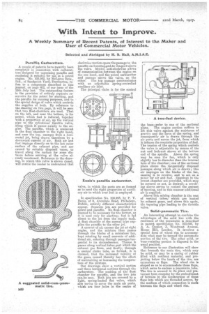
A couple of patents have recently been completed in connection with carburetters designed for vaporizing paraffin and rendering it suitable for use in ii petrol engine. No. 103,942, by lielcLaren Bros., Ltd., of Sandpoint Yard,. Dumbarton, refers to a component described in this journal, on page 402, of our issue of the 13th July last. Tim outstanding feature is the provision of entirely separate reservoirs for the petrol for starting, and the paraffin, for runningpurposes, and to the special design of valve which controls the supplies of both. By reference to the drawing on this page, it will be seen that two float-chambers are used. That on the left, and near the bottom, is for petrol, which fuel is induced, together with a proportion of air, up the vertical pipe to the cylindrical throttle valve, along which it passes axially to the engine. The paraffin, which is contained in the float chamber to the right hand, and near the top, emerges from a horizontal jet, being drawn therefrom by a downward current of air. Both air and fuel impinge directly on to the hot outer surface of the exhaust pipe, and are caused by suitably disposed vanes, to travel along the surface for some distance before arriving at the valve already mentioned. Reference to the drawing, in which this valve is shown closed, will enable the reader to understand that clockwise 'motion opens the passage to the paraffin carburetterand..to theportvabove the valve. Motion, anti-clockwise allows of eammunicationihertween the engine on the one hand, and the petrol carburetter and passage above the valve, on the other. The top passage communicates with an adjustable spring-controlled auxiliary air inlet.
The principal claim is for the control valve, in which the ports are so formed as to send the right proportion of auxiliary air to which ever fuel is employed.
In specification No. 103,973, by P. V. Ennis, of 8, Avondale Road, Phibsboro, Dublin, entirely different characteristics appear. Separate jets are provided for petrol and paraffin. No float chamber is deemed to be necessary for the former, as it is used only for starting; fuel is fed direct to the jet from the supply tank. A float chamber of the normal type supplies the paraffin to the other jet.
A current of ail' crosses the jet at right angles, and the mixture then passes through the blades of a miniature fan, kept rotating by small currents of additional air, entering through passages tangential to its circumference. Thence it passes along vertical tubes past which the exhaust gas flows, and finally, through a conical choke tube, so formed, it is claimed, that the increased velocity of the gases caused thereby has the effect of maintaining or increasing the temperature of the mixture.
Our drawings show a vertical section and three horizontal sections through the carburetter. The position of the float chamber for paraffin, and the two jets can.be seen. Both jets are covered by a light, spring-loaded flat valve, which also serves to cover the main air parts,
whisk are four holes in the centre of
the base—refer to one of the sectional
plans. The engine suction suffices to lift this valve against the resistanoe of gravity and the force of the spring, and consequently air is drawn through the air ports and across the jet, from which it induces the requisite proportion of fuel. The tension of the spring which controls the valve is adjustable by means of the nut and lock-nut shown at the bottom end of the spindle. Above the spring may be seen the fan, which is only slightly less in diameter than the internal bore of the chamber ; one of the sectional plans shows the• tangentially disposed passages along which air is drawn; this air impinges on the blades of the fan, causing it to revolve and to act as a mixer for air and fuel. Openings in the lowest chamber are provided, which may be covered or not, as desired ; a revolving sleeve serves to control the amount of opening, and in this manner additional air is supplied.
Above this mixing chamber is the nest of vertical tubes; which are heated by exhaust gases, and above this again, the tapering pipe leading to the throttle valve.
Solid-pneumatic Tire.
An interesting attempt to combine the advantages of the solid tire with the resilience of the pneumatic is described in patent specification No. 103,694, by A. A. Crozier, 3, Woodwest Avenue, Rome sill, London. It involves a special form of wheel rim to accommodate what may be termed the pneumatic portion of the tire. The other solid, or wear-resisting portion is disposed in the usual position.
Reference to our illustration will show that beneath the main tire, which may be solid, or may be a casing of rubber filled with resilient material, and projecting below the heads of the tire, are extensions or flaps. The wheel rim is shaped so as to accommodate these flaps, which serve to enclose a pneumatic tube. The tire is secured in its place and prevented from creeping by the embodiment of ferrules in the construction of these flaps into which are threaded screws, by the medium of which connection is made between the flaps and wheel rim.