


An Engine-cum-transmission Unit
Page 56
If you've noticed an error in this article please click here to report it so we can fix it.
pATENT No.. 652,422 comes from Regie Nationale Des Usines Renault, Billancourt, France, and shows a complete power and transmission unit occupying a minimum of space. It is equally suitable for either -a frontor rear-driven vehicle.
The engine (1) carries the gearbox (2), which has its output shaft (3) at one side The shaft doubles back alongside the engine, on the side of which is mounted the final bevel and differential gear (4). The axle shafts (5) project normally, but one of them has to pass through the sump to emerge on the opposite side. This is arranged without fouling by arranging for the shaft axis A PNEUMATIC SUSPENSION SYSTEM
PATENT No. 652,698 comes from Soc. D'Inventions Aeronautiques et *152.698 Mecaniques S.I.A.M., Geneva, Switzerland, and discloses details of a pneumatic suspension scheme. The system is arranged to permit the axles a constant deflection, whether the load be light or heavy; this means that the " hardness " . • of the system automatically adjusts itself. The drawing shows, diagrammatically, the general layout. Each wheel is attached to a plunger (I) which rises or falls in a closed cylinder (2) containing trapped air which acts as the spring. The lower part of the cylinder is filled with oil or other liquid.
The response of the system varies in accordance with the quantity of trapped air, and this is made to vary, in turn, with the applied load. The air is compressed by a pump (3) and stored in a receiver (4), and its admission to the cylinders is controlled by levers (5). One of these oscillates with the front axle, the other with the rear. If the axle deflections are larger than normaL'a valve attached to each lever admits more air, thus hardening the suspension. If, however, the load be insufficient to cause standard deflection, the valves permit fluid to escape and return to the storage tank (6). The fluid is returned to the cylinders via the air line, because when the fluid level rises in the tank it eventually reaches the hooded intake 7 of the air-pump and is sucked over with the air.
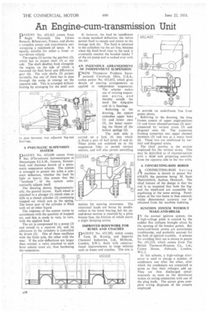
AN INGENIOUS ARRANGEMENT OF INDEPENDENT SUSPENSION
FROM Thompson Products Incorporated, Cleveland, Ohio, U.S.A., comes patent No. 652,432, which gives details of steering arrangements as applied to independent suspension.
The scheme makes use of existing suspension parts, and :hereby avoids the need for king-pins and thir bearings_ Referring to the drawing, the system embodies upper links (1) and lower ones (2), the latter receiving the thrust of the helical springs (3).
The stub axle is carried on a fork (4) into which is fitted a pair of ball joints (5 and 6). These joints are socketed on to the suspension links to permit vertical motion, and will also permit swivelling motion for steering movement. The rotational loads are borne by needlerollers in the lower bearing, but the opand-down motion is received by a plain bronze face, the friction of which exerts a slight damping action.
IMPROVED BODYWORK FOR BUSES AND COACHES
PATENT No. 652,202, which comes from M. Koenig, and Imperial Chemical Industries, Ltd., Millbank, London, S.W.I, deals with constructional improvements in large vehicles such as buses and coaches. The aim is
to provide an underframe free from gusset plates.
Referring to the drawing, the long frames consist of upper angle-sections (I) and lower channel-sections (2) interconnected by vertical struts (3) and diagonal ones (4). The transverse framing comprises two upper channel members (5) and two at a lower level (6). These two are reinforced by vertical and diagonal struts.
The chief ,novelty is the section employed for the vertical struts. This may be desCribed as of channel-section with a third web projecting centrally from the opposite side to the two webs.
A CONNECTING-ROD BORER
ACONNECTING-ROD boring machine is shown in patent No. 650,839, the patentee being M. Sccst Mastinfabrik, Aarhus, Denmark. The chief feature of the design is that the rod is so mounted that both the bigand the 'small-end are accessible for machining at the same setting. Parallelism of the two bores is thus ensured, whilst dimensional accuracy can be obtained from the machine indexing.
IGNITION SYSTEM WITHOUT MAKE-AND-BREAK I N the normal ignition system, the high-voltage pulse is created by the sudden flux collapse brought about by the opening of the breaker points. But make-and-break points are notoriously troublesome, and probably account for the bulk of ignition troubles. A scheme for avoiding their use is shown in patent No. 651,219, which comes from The British Thomson-Houston Co., Ltd., Crown House, Aldwych. London, W.C.2.
In this scheme, a high-voltage alternator is used to charge a number of condensers one after the other, after which the condensers are connected in series so that their voltages add up. They are then discharged simultaneously as soon as the distributor makes an arcing connection with one of the plug leads. The patent gives complete wiring diagrams of the circuits employed.