


Novel Method of Body-building
Page 36
If you've noticed an error in this article please click here to report it so we can fix it.
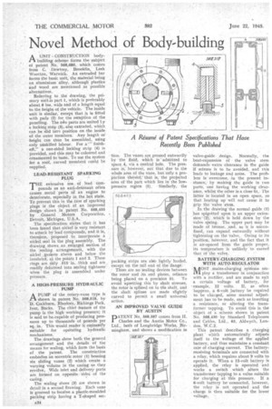
II.A UNIT CONSTRUCTION bodybuilding scheme forms the subject of patent No. 598,680, which comes from C. Dawtrey, Brooklin, Leek Wootton, Warwick. An extruded bar forms the basic unit, the material being an aluminium alloy, although plastics and wood are mentioned as possible alternatives.
Referring to the drawing, the primary unit As part 1, which is preferably about 6 ins, wide and of a length equal to the height of the vehicle. The inside
• unit is similar, except that it is fitted with pads (2) for the recePtion of the panelling. The to parts are united ty a locking strip (3), also extruded, which can be slid int,) position on the insider of the outer members. Any length or height can thus be assembled, using only unskilled labour. For a" finishoff," a one-sided locking strip (4) is provided, and this may be coloured and ornamented to taste. To use the system for a roof, curved member could, be
supplied. • LEAD-RESISTANT SPARKING PLUG
THE extensive use of lead compounds as an anti-defoiaant often causes metal parts of an engine to deteriorate, especially in the hot state. To prevent this in the 'case of sparking plugs is the object of an improved design shown in patent No. 568,455 by General Motors Corporation, Detroit, Michigan, U.S.A.
The specification, states that it has been found that nickel is very resistant to attack by lead compounds, and it is, therefore, proposed to incorporate a nickel seal in the plug assembly. The drawing shows an enlarged section of the 'sealing arrangement's, with the nickel gaskets above and below, the insulato, at the points 1 and 2. These rings are only .015' in.. thick and are readily deformed into sealing tightness when the plug is assembled under pressure.
A HIGH-PRESSURE HYDRAULIC PUMP
APUMP of the rotary-vane type is shown in patent No. 568,518, by Is, Cockburn, Rhodora, Richings Park, Iver, Bucks. The chief 'feature of the pump is the high working pressure; it is said to bescapable of producing pressures up to thousands of poUnds per sq. in. This would render it eminently suitable for operating hydraulic mechanisms.
The, drawings show both the general arrangement and the details a the means for sealing, which form the basis of the patent. The construction embodies an eccentric rotor (1) housing six sliding vanes (2) which create a varying volume in the casing as they revolve, Wide inlet and delivery ports are formed on opposite sides of the casing. The sealing shoes (3) are shown in detail in a second llrawing. Each vane is grooved to teceive a plastic-moulded packing strip having a T-shaped sec
lion. The vanes are pressed outwardly by the fluid, which is ' admitted to space 4, via a central hole. The pressure is, however, not that due to the whole area of the vane, but only a proportion thereof; that is, the projected area of the part which lies in the lowpressure region (5). Similarly, the packing strips are AK° lightly loaded except on the tail end of the flange. There are no' sealing devices between the rotor •and its end plates, reliance being placed on a precision fit. To avoid upsetting this by shaft stresses, the rotor is splined on to the shaft, and the shaft splines are made slightly curved to permit a small universal action.
AN IMPROVED VALVE GUIDE BY AUSTIN DATENT No. 568,587 comes from H. / Charles and the Austin Motor Co., Ltd., both of Longbridge Works, Birmingham, and shows a modification in
valve-guide design, Normally, the heat-expansion of the valve stem dentands extra clearance in the guide if seizure is to be avoided, and this leads to leakage and noise. The problem is overcome, in the present instance,. by making the guide in two parts, one having the working clearance, whilst the other is a close fit. The latter islocated in an open space, SO that heating up will not cause it to grip the valve stem.
In, the drawing the normal guide (7) has spigotted upon it an upper extension (2); which is held down by the valve spring. The upper part may be
made of bronze, and,, it is unconfined, can expand ouwardly without tightening on the valve. Owing to its "position, hciwever, and the fact that it is air-spaced from the guide proper, its temperature is unlikely to exceed that of the valve.
BATTERY-CHARGING SYSTEM WITH AUTO-REGULATOR
MOST mains-charging systems employ a transformer in conjunction with a rectifier, and are made to suit a certain voltage of battery, Mr example, 12 volts, If, as often happens, a 6-volt „liattery be required to be charged, some manual adjustment has to be made, such as inserting a resistance, or altering the transformer tapping. To avoid this is the object of a scheme shown in patent No. 568,430 by Standard Telephones and Cables, Ltd., 63, Aldwych, London, W.C.2.
This patent describes a charging plant which automatically adjusts itself to the voltage of the applied battery, and thus maintains a constant rate of charging current. The battery. receiving terminals are connected with a relay, which requires about 9 volts to operate it. When a 12-volt battery is applied, the relay is operated and works a switch which alters the transformer tapping to a value suitable for charging at this pressure. If a 6-volt battery be connected, however, the relay is not operated and the . charge is then suitable for the lower voltage.