


Patents Completed.
Page 22
If you've noticed an error in this article please click here to report it so we can fix it.
Complete specifications of the following patents will be sent to any address in the United Kingdom upon receipt of eightpence per copy at the Sales Branch, Patent Office, Holborn, W.C.
DRIVING AXLE. — Selbach and Others.—No. 14,670, dated 10th July, 1908.—This invention relates to live axles for motorcars, and comprises a divided cardan shaft, two ends of which are situated within a hollow drum that revolves in ball bearings and is driven from the gearing of the car, and the opposite ends are connected to spiders which engage with the hubs of the driving wheels. This arrangement results in bringing the ends of the divided cardsn shaft as near as possible to the centre of the main driving shaft, well within the casing of the differential gear, and as near as possible to the middle of the axle. This disposition of the parts ensures the maximum length of driving shaft and efficiency of drive, without necessitating the use of long bearings. This invention may be applied to systems of single or double reduction with or without differential gear.
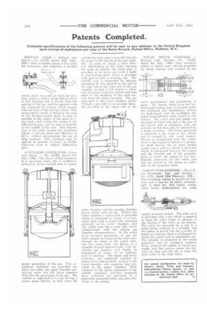
ACETYLENE GENERATOR—Lucas and Others. — No. 14,902, dated 14th July, 1908.—The object of this invention is to minimize waste due to ineffective utilization of the carbide and to ensure
steady generation of the gas. Two cylindrical chambers are provided one above the other, the upper chamber containing water and the lower chamber being for the generation of the gas. The carbide is supported in a cage having a coarse gauze bottom, so that when the
carbide has been used it may fall through the gauze to the bottom of the gas chamber. In order to obtain a more effective distribution of the water through the mass of carbide, the water pipe is provided at its lower end with a baffle or distributing plate which is provided with grooves and a covering cap. The carbide cage is suspended by springs, consisting of wire secured at one end to the cage and at the other end to the gas chamber, so that it will receive a vibratory movement from the vehicle and thus assist in the shedding of the used carbide from the active material. The gas generated in the lower chamber passes through a gas tube to an annular chamber provided at the upper end of the water chamber arid this annular chamber has an outlet valve or tap. Within the water chamber a water lock is provided which is connected by means of a horizontal tube with a sealed tube arranged externally of the water chamber, and this sealed tube has a vent tube which communicates with the annular gas chamber aforementioned. In the event of an excessive generation of gas the latter escapes by means of the vent tube, through the water in the sealed tube, into the water lock, and thence to a chamber located concentrically with the annular gas chamber and finally to atmosphere by means of an ordinary vent or opening. The upper and lower chambers are connected together by means of tie-rods pivotally secured to the lower chamber and engaging lugs provided on the upper chamber. With reference to the spring suspension of the carbide container, previous proposals have embodied the provision of a separately-suspended sifter, movable relatively to the casing. STEAM MOTOR VEHICLES. -Pearson and Another.--No. 14,228, dated 4th July, 1908.—This invention relates to motor road vehicles propelled by steam engines and consists in the novel arrangement and positioning of parts. The engine, which is of the vertical single-acting type, is located under the footboard and immediately behind the dash-board, with its crankshaft disposed longitudinally with respect to the vehicle. The water and fuel pumps are arranged at either side and to the rear of the engine and in alignment with one another, so that they may be operated by a single eccentric. The steam generator is mounted in the front of the vehicle and is covered by the usual bonnet. Motion is transmitted from the crankshaft to the engine by means of a propeller shaft having one or more cardan joints, and a positive clutch is provided which is interposed between the engine and the forward end of the propeller shaft to enable the engine to run free Suitable reservoirs for the water and fuel are carried by the frame on either side of the propeller shaft.
LIQUID-FUEL BURNERS—The S. N. Car Syndicate, Ltd., and Another.— No. 4,131, dated 19th February, 1909.— This invention relates to liquid-fuel burners, and it has for its object automatieally to clean the fuel nozzle which, when heavy hydrocarbons are used, rapidly becomes choked. The inlet valve is provided with a pin which is adapted to enter the valve orifice in advance of the closing of the valve on its seating. The valve is connected by a rod to a small piston working in a cylinder, and the piston is forced into the cylinder by means of a spring which is interposed between the piston and an adjustable nut. The cylinder is connected to the steam generator, and on excessive pressure being attained the piston is forcsd outwards, and this motion causes the fuel valve to close and the pin to clear the inlet orifice of the inlet valve.