


SOME CARBURETTER IMPROVEMENTS.
Page 28
If you've noticed an error in this article please click here to report it so we can fix it.
A Résumé of Recently Published Patents.
THE PRINCIPLE of the carburetter improvement which is the subject of specification No. 207,086, the patentee being E. Dodson, has its basis in the fact that a simple jet nozzle, • located_ in the choke tube of a carburetter, has an outflow rate which increases faster than the rate of flow of the air through the choke. If, however, the jet nozzle is not within the choke tube, but communicates with it by a passage in which air can mingle with the liquid delivered by-the, jet, then, if this passage be of relatively small bore, the fluid friction within it increases at a greater rate than it doee in
the larger bore of the choke tube, so that the characteristic delivery from the jet is considerably inorlified, and, in effect, its rate of increase may actually be mueh slower than that of the air through the choke.
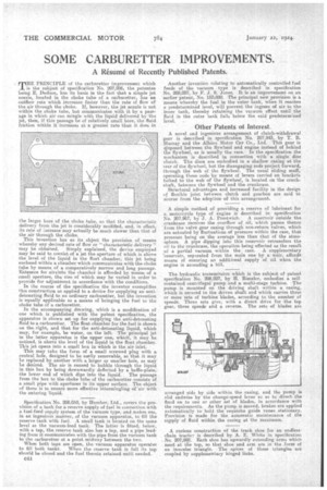
This invention has as its object the provision of means whereby any desired rate of flow or "characterietic delivery" may be obtained. Simply explained, the device employed may be said to consist of a jet the aperture of which is above the level of the liquid in the float chamber, this jet being enclosed within a chamber which communicates with the choke tube by means of a comparatively narrow and long passage. Entrance for airtinto the chamber is afforded by meant; of a small aperture, the size of which may be varied in order to provide for adjuStanent in accordance with the condilions. In the course of the specification the inventor exemplifies his construction as applied to a device for supplying an antidetonating fluid to an ordinary carburetter, but the invention is equally applicable as a means of bringing the fuel to the choke tube of a carburetter.
In the accompanying drawing, which is a modification of one which is published with the patent specification, the apparatus is shown set up for supplying the anti-detonating fluid to a carberetter. The float chamber for the fuel is shown . on the right, and that for the anti-detonating liquid, which may, for example, be water, on the left. The principal jet in the latter apparatus is the upper one, which, it may be noticed, is above the level of the liquid in the float chamber-This jet opens into a small box in which is the air inlet.
This may take the form of a small screwed plug with is central hole' designed to be easily removable, so that it may he replaced by another with a larger ey smaller hole, as may Fe desired. 'The air is caused to bubble through the liquid in this box by being downwardly defleeted by a baffle-plate, the lower end of which dips into the liquid. The passage from the box to the choke tube of the carburetter consists of a small pipe with apertures in its upper surface. The object of these is to ensure more effective intermingling of 'air with the entering liquid.
Specification No. 208,050, by Humber, Ltd., covers the provision of a tank for a reserve supply of fuel in connection with a fuel-feed supply system of the vacuum type, and snakes use, in an ingenious manner, of the vacuum apparatus, to -fill the reserve tank with fuel. A small tank is located on the same level as the vacuum-feed tank. The latter is fitted; below, with a tap, the reserve tank also has a tap, and a pipe leading from it communicates with the pipe from the vacuum tank to the carburetter at a point midway between the two. When both taps are open, the vacuum apparatus operates to fill both tanks. When the reserve tank is full its tap should be closed and the fuel therein retained until needed. C44
Another invention relating to automatically controlled fuel feeds of the vacuum type is described in specification No. 208,087, by F. J. S. Jones. It is an improvement on an earlier patent, No. 152880. The principal new provision is a means whereby the fuel in the outer tank, when it reaches a predetermined level, will prevent. the ingress of air to the inner tank, thereby retaining the vacuum effect until the fluid in the outer tank falls below the said predetermined level.
Other Patents of Interest.
A novel and ingenious arrangement of clutch-withdrawal gear is described in specification No. 207,943, by T. B. Murray and the Albion Motor Car Co., Ltd. This gear is disposed between the fly-wheal and engine instead of behind the flywheel, as is usually the case. In the specification the mechanism is described in connection with a single disc clutch. The discs are embodied in a shallow casing at the rear of the flywheel, but the disengaging rods project forward, through the web of the flywheel. The usual sliding muff, operating these rods by means of levers Carried on brackets bolted to the web of the flywheel, is located on the crankshaft, between the flywheel and the crankcase.
Structural advantages and increased facility in the design of flexible joint between clutch and gearbox are said to accrue from the adoption of this arrangement A. simple method of providing a reserve of lubricant for a motorcycle type of engine is described in specification
No. 207,967, by J. A. Prestwich. A reservoir outside. the crankcase receives the overflow of oil, which passes thence from the valve gear casing through non-return valves, which are actuated by fluctuations of pressure within the case, that pressure being on the average less than that of the atmosphere. A pipe dipping into this reServOir retransfers the nil to the crankcase, the operation being effected as the result of a partial vacuurn within the case. A supplementary reservoir, separated from the main one by a weir, affords meant; of ensuring an additional supply of oil when the engine is ascending a hill.
The hydraulic transmission which is the subject of patent specification No. 208,027, by H. Rieseler, embodies a selfcontained centrifugal pump.and a multi-stage turbine. The pump is mounted on the driving shaft within a casing, which is secured to the drivers shaft and which carries three or more sets of turbine blades, according to the number of speeds. Three sets give, with a direct drive for the top gear, three speeds and a reverse. The sets of blades are arranged side by side within the casing, and the pump is slid endwise by the change-speed lever so as to direct the fluid on to one or other set of blades, in accordance with the requirements. As the pump is moved, brakes are applied automatically to hold the requisite guide vanes stationary. Provision is made for the automatic maintenance of the supply of fluid within the casing at the maximum.
A curious construction of the track shoe for an endless' chain tractile is described by A. E, White in specification . No. 207,992, Each shoe has upwardly extending arms which meet at tlie top, so that shoe and arm are in the form of an isosceles triangle. The apices of these triangles are coupled by suPplernentary hinged links.