


MAKING BEST USE OF THE - FORD.
Page 23
If you've noticed an error in this article please click here to report it so we can fix it.
Valuable Advice on Every Phase of Ford Transport, which will Appeal to the Owner, Driver, and Repairer.
IN THIS series of hints concerning the Ford light chassis and ton truck wherever they are employed for commercial purposes, we endeavour to deal with the subject from every view-point, so that the advice given will appeal to the owner, driver, maintenance engineer, or mechanic. Valuable sources of information are being tapped for this purpose, and it should be understood that the advice given will be derived from those with an intimate knowledge of the subject.
We shall welcome for inclusion among the hints those which have proved of value to individual users, and will make suitable remuneration for any published. What we desire are the results of practice.
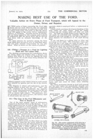
160.—Fitting a Dynamo to a Ford for Lighting Head and Tail Lamps Only.
The drawing accompanying this contribution shows the wiring which was utilized when a dynamo and battery were fitted to a .Ford for lighting the head and tail lamps, the oil side lamps being retained, the ordinary magneto on the vehicle doing no work except that entailed by ignition and the use of the electric horn.
The diagram is almost self-explanatory, and the lighting switch is used only for "or'," dim," and " off " positions for the headlamps, the magneto switch on the instrument board being used for the tail lamp, which, incidentally, is the ordinary oil lamp with an electric light adapter. The generator, etc., are grounded in the ustal manner ; the battery itself is placed under the rear seat.
161.—The Care of the Ford Mileometer and How to Repair It.
One of the most popular types of mileometers employed on the Ford vehicle is the Stewart. It is of simple construction but, as with all other things, after a long life, it requires a certain amount of attention and slight repairs to renew its efficiency. The drive is attached to a steering arm, and has a small fibre pinion meshing with a large driving pinion fitted over the wheel hub bolt heads and held in position by small round-head wood screws inserted into the spokes. There must be at least *-in. clearance at the roots of the teeth when the pinions are in .position. If too deeply in mesh, the teeth of the fibre pinion may be broken away.
If such ail accident occurs, the fibre wheel can easily be replaced by removing the centre setscrew which supports the swivel arm and disconnecting the cable casing. The wheel is simply a tight fit on the collar and provided with a centre split-pin. It is worth noting that there are three different pitches of fibre pinions used with the Ford; and it is necessary to ascerta.in which is -employed before a replacement is effected.
A fault which sometimes develops is breaking of the links within the cable casing. Hold the casing vertical and the broken cable will slide out each way. The links are simply double hooks, and any one can easily be unhooked and replaced. The cable should be just long enough for one link to project a short distance for attachment of the small driving head.
At one end there is a sliding joint to allow end movement of the cable. This sometimes wears and twists oft, but a new joint can easily be made. If a replacement be not available, a suitable piece of sheet steel can be cut to size and filed to shape.
There is a little stop peg riveted into this sliding joint in order to keep it, within the driving sleeve.
The swivel device is quite simple. It contains three working Parts, consisting of a small skew driving pinion, an intermediate bevel wheel and the bevel drive for the cable. The whole arrangement is held together by two collars driven over pins, and a small taper pin anchors tinecable drive. The chief trouble occurs at the swivel joint, which develops excessive play due to wear, thus throwing the two bevel wheels out of pitch and gradually wearing away the teeth. Some of the play can be reitiove.a.by, tightening the bottom collar, but if too
tight this i
locks the swivel motion, and t should be left Set that-the wheels are just free. To, dismantle the swivel, drive out the centre pin through the collar, holding the body firmly over a vice. it will then come a-part, disclosing the small driving wheels, etc. The cable 'bevel wheel can be removed by knocking out the small taper pin at the side of the body. When removing the driving skew .gear, withdraw the fibre pinion and drive it out through the collar, which must only be done when the swivel is dismantled. The gears are made in several types, and care must be taken when ' ordering renewals.
The whole mechanism should be kept well greased and the cable taken out periodically, cleaned, and greased before it is returned, otherwise -undue wear_ and friction will be set LiD between the links and their casing.