


Patents Completed.
Page 22
If you've noticed an error in this article please click here to report it so we can fix it.
Leaf-spring Lubrication. Self-aligning Bearings. Improving the Brakes.
M. SCFM.DGE.—No. 25,145, dated 4th November, 1913.— The leaf-springs are opened out by a wedge-piece and a screw mounted in a U-shaped frame. The wedge is located between two leaves, and the screw turned to force it. in and separate the leaves.
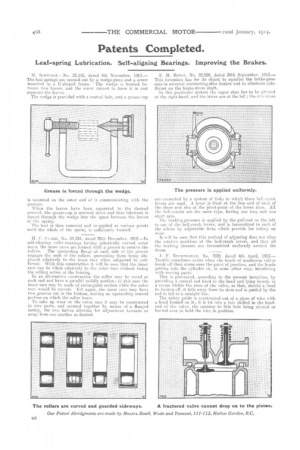
The wedge is provided with a central hole, and a grease-cup is mounted on the outer end of it commuMcating with the passage.
When the leaves have been separated to the desired amonot, the grease-cup is screwed down and thus lubricant is forced through the wedge into the space between the leaves of the spring. The tool is then removed and re-applied at various points until the whole of the spring is sufficiently treated.
H. C. Cr,Araz, No. 27,334, dated 28th December, 1912. —In self-aligning, roller-bearings having spherically curved outer races, the inner races are formed with a groove to receive the
rollers. The upstanding flange at each side of the groove engages the ends of the rollers, preventing them being displaced relatively to the inner race when subjected to endthrust. With this construction it will he seen that the inner race can he tilted relatively to the outer race without losing the rolling action of the bearing.
In an alternative construction the roller may he coned at each end and have a parallel middle portion; in this ease the inner race may be made of rectangular section while the outer race would be curved. Yet again, the inner race mayhave two grooves cut in the bottom, leaving an upstanding central portion on which the roller bears.
To take up wear on the outer race it may be constructed in two parts, and secured together by means of a flanged casing, the two halves allowing for adjustment towards-or a vay from one another as desired.
F. H. Royce, No. 22,020, dated 30th September, 1913.— This invention has for its object to equalize the brake-pressure in external contracting-shoe brakes and to eliminate side. thrust on the brake-dram shaft.
In this particular system the upper shoe has to be pivoted at tho riLkt-liand„ and the lower one at the left.; the two shoes are connected by a system of links in which three lieli-erank levers are used. A lever is fixed at the free end of each of the shoes and also at the pivot-point, of the lower shoe. All the bell-cranks are the same type, having one long and one short arm.
The braking-pressure is applied by the pull-rod on the left to one of the bell-crank levers, and is transmitted to each of the others by adjustable links which provide for taking up wear.
It will be seen that this method of adjusting does not alter the relative positions of the bell-crank levers, and that all the braking stresses are transmitted uniformly around the drum.
J. F. T3i7exiNGnAm, No. 7928, dated 4th April, 1913.-Trouble sometimes arises when the heads of mushroom valves break off their stems near the point of junction, and the heads getting into the cylinder n'r, in some other way, interfering with moving park.
This is prevented, according to the present invention, by providing a central rod fixed to the head and lying loosely iii a recess within the stem of the valve, so that, should a head be broken off, it fails away from its stem and is guided by the rod to fall in a straight line.
The safety guide is constructed out of a piece of wire with a head formed on it; it is let into a hole drilled in the headend of the valve, the opening to this hole being riveted or burred over to hold the wire in position.