


New Features in a Heavy-duty Six-wheeled Mobile Crane
Page 43
If you've noticed an error in this article please click here to report it so we can fix it.
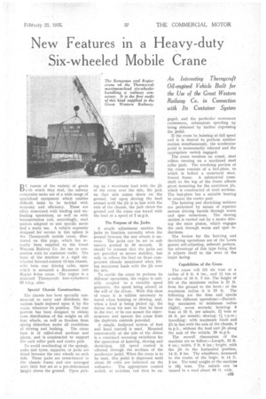
An Interesting Thornycroft Oil-engined Vehicle Built for the Use of the Great Western Railway Co. in Connection with Its Container System
DY reason of the variety of goods L./with which they deal, the railway companies make use of a wide range of specialized equipment which enables difficult tasks to be tackled with economy and efficiency. These are often concerned with loading and unloading operations; as well as with transportation and, accordingly, road motors adapted to suit specific needs find a ready use. A vehicle expressly designed for service in this sphere is the Thornycroft mobile crane, illustrated on this page, which has recently been supplied .to the Great • Western Railway Co. for use in connection with its container traffic. The basis of the machine is a rigid sixwheeled forward-control 12-ton chassis, with twin rear driving axles, upon which is mounted a ,Ransomes and Rapier 6-ton crane. -The engine is a standard Thornycroft four-cylindercd 82 b.h.p. oiler.
Special Chassis Construction.
The chassis has been specially constructed to carry and distribute the various loads imposed upon it by the ciane, whatever its position. The rear portion has been designed to obtain even distribution of the weight on all four wheels, as well as freedom from spring distortion under all conditions of driving and braking. The crane base is of rolled-steel sections and plates, and is constructed to support the rack roller path and centre post.
To avoid overloading of the springs, axles and tyres, supports, or jacks are fitted between the rear wheels on each Side. These jacks are cross-braced to the chassis frame and are arranged with their feet set.at a pre-determined height above the ground. Upon pick ing up a maximum load with the jib of the crane over the side, the jack on that side comes down on the ground, but upon slowing the load around until the jib is in line with the axis of the chassis, the jack clears the ground and the crane can travel with the load at a speed of 2 m.p.h.
The Purpose of the Jacks.
A simple adjustment enables the jacks to function correctly when the ground between the rear wheels is uneven. The jacks can be set to suit uneven ground in 30 seconds. It should he stressed that the jacks are' not provided to secure stability, but only to relieve the load on those components already mentioned when lifting maximum loads with the jib over the side.
To enable the crane to perform its different operations, the engine is suitably coupled to a variable speed generator, the speed being altered at the will of the driver.... With this class of crane it is seldom necessary to travel when hoisting or clewing, and, when a load is being picked up, the driver turns his seat so that he faces to the rear, or he can mount the superstructure and operate the crane from the duplicate controls provided.
A simple, foolproof system of foot and band control is used. Mounted conveniently at the side of the driver is a combined reversing Switchbox for the operations of hoisting, skwing and derricking. All speed control is effected through the medium of the accelerator pedal. When the crane is to be used, this pedal is depressed until about 50 volts are indicated on the voltmeter. The appropriate control switch, or switches, can then be en gaged, and the particular movement commences, subsequent speeding up being obtained by further depressing the pedal.
If the crane be hoisting at full speed and it is desired to perform anbther motion simultaneously, the accelerator pedal is momentarily released and the appropriate switch engaged.
The crane revolves on coned, steel rollers running on a machined steel roller path. The revolving portion of the crane consists of a bed-plate, to which is bolted a structural steel, braced frame. A substantial crossshaft at the top of the frame affords pivot mounting for the cantilever jib, which is constructed of steel sections. The bed-plate has a suitable bearing to receive the centre post.
The hoisting and derricking motions are performed by means of separate motors driving barrels through worm and spur reductions. The slewing motion is carried out by a motor driving the main pinion, which engages the rack through worm and spur reductions.
The brakes for the hoisting and derricking operations are of the Lewis patent self-adjusting, solenoid pattern, the advantage of this type being that it adjusts itself to the wear of the brake facing.
Capabilities of the Crane.
The crane will lift six tons at a radius of 9 ft. 6 ins., and 1:1 ton at a radius of 16 ft. 7 ins. The height of lift at the minimum radius is 21 ft. from the ground to the hook ; at the maximum radius it is 10 ft. The following are the time and speeds for the different operations:---Derricking: maximum to minimum radius (light), seven seconds; hoisting: 6 tons at 23 ft. per minute, 21 tons at 45 ft. per minute; slewing: 1 r.p.m.; travelling: with maximum loads and jib in line with the axis of the chassis, 2 m.p.h., without the load and jib along the axis of the vehicle, 20 m.p.h.
The overall dimensions of the machine are as follow:—Length, 22 ft. 6 ins.; width, 7 ft. 6 ins.; height, with the jib in the horizontal position, 14 ft. 6 ins. The wheelbase, measured to the centre of the bogie. is 14 ft. 3 ins. The total weight of the machine is 18i tons. The vehicle can be turned in a road about 60 ft. wide.