


Patents Completed.
Page 28
If you've noticed an error in this article please click here to report it so we can fix it.
Complete specifications of the following patents will be sent to any address in the United Kingdom upon receipt of eightpence per copy at the Sale Branch, Patent Office, Holborn, W.C.
Automatic Speed Control.
Jennings Scott McComb.—Na. 10,630. dated 2nd May, 1911.—The object of this invention is to provide an adjustable, simple, and efficient means of preventing a motor vehicle's being driven above a certain predetermined speed. The control is effected on the fuel supply, and is operated from the speedometer. A valve is provided in the fuel-supply pipe between the tank and the carburetter, arid this is out of the control of the driver, being controlled solely by a lever attached to a gearwheel meshing with another carried by the pointer of the speedometer. As the speed rises this lever moves dowuwards and depresses the valve, causing it to shut off the supply a certain amount. The preferred construction of valve comprises a hollow tube, spring supported. and provided with a number of holes of varying sizes. These holes are successively brought, to register with the inlet and outlet-valve ports. A number of holes is proviied to allow of adjustment of the maximum speed, and in one construction the tube is formed with series of holes at right angles to one another, and the tube is guided in its vertical movement so that by releasing the guide and turning the tube through 90 degrees, a still greater range of maximum speeds may be obtained.
A Dunlop Detachable Wheel.
The Dunlop Pneumatic Tyre Co., Ltd., and Walter Wright.—No. 1740, dated 23rd January, 1911, Cognate Application No. 9738/11.—In this specifiration a detachable wheel is described, comprising the ordinary inner fixed hub and outer detachable hub which are
coupled together by peripheral teeth or serratious and are secured relatively to one another by a locking nat. This nut is screwed on to the inner hub and has screwed on to its inner end a small nut which grips, between itself and a shoulder on the locking nut, an inwardly. turned flange on the detachable hub. The locking device comprises a springcontrolled push piece concentric with thli axis of the wheel and movable axially but not rotatably on it. This ring normally engages the nut on the inner huh, hut van be displaced so as to unlock the out, so that the latter can be rotated for detaching thewheel. Teeth are provided on the pushpiece and are held in engagement by springs which are compressed by the spanner when the locking nut is being detached.
Horse Transport by Motor Vehicle.
James Dime11.--No. 4773, dated 25th February, 1911.---This vehicle is provided especially fur carrying horses, but is also suitable for other animals. An ordinary chassis is provided ; the body part has hinged sides which are adapted to be let down so as to form an inclined platform for ease in loading and unloading the vehicle. Brackets are secured to these uprights by which
their inclination may be varied according to circumstances. Hinged partitions are provided in the van, and these are secured to uprights by which the interior of the vehicle is divided into stalls. The uprights are preferably hinged together in two parts, the upper part being adapted to turn as shown in dotted lines and being fixed when in its upright position by entering a channel in the roof. Accommodation is also provided for those accompanying the horses, in a compartment towards the front, of the vehicle.
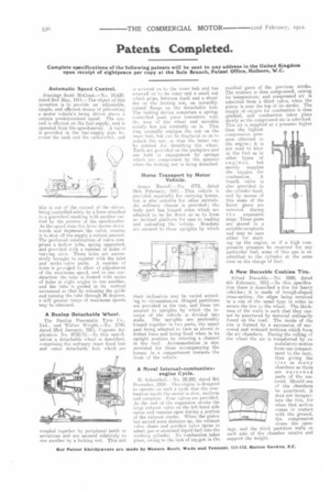
A Novel Internal-combustionengine Cycle.
H. Schneebeli.—No. 28.582, dated 8th December, 1910.-this engine is designed to operate on such a cycle that the combustion inside the motor is slow, uniform and complete. Foos valves are provided. At the end of the expansion stroke the large exhaust valve on the left-hand side 41,elis and remains open during a portion if the exhaust stroke. When the piston has moved some distance up, the exhaust valve closes aud another valve opens to admit gas or atomized liquid fuel into the working cylinder. No combustion takes place, owing to the lack of oxygen in the residual gases of the previous stroke. The mixture is then compressed, raising its temperature, and compressed air is admitted from a third valve, when the piston is near the top of its stroke. The
i
supply of oxygen for combustion s thus gradual, and combustion takes place slowly as the compressed air is admitted. This air is supplied at a pressure higher than the highest compression pressure obtained in the engine; it is not used to blow in the fuel as in other types of engines, but merely supplies the oxygen for
combustion. A fourth valve is also provided in the cylinder head, and by means of this some of the burnt gases are removed during
t lie expansion stage. These gases are' stored in a suitable receptacle anti may be used either for starting up the engine, or if a high compression pressure be required for any particular fuel, some of this gas is readmitted to the cylinder at the same time as the charge of fuel.
A New Ducasble Cushion Tire.
Alfred Ducasble.—No. 2998, dated 6th February, 1911.—In this specification there is described a tire for heavy vehicles; it is made of trough-shaped cross-section, the edges being received in a rim of the usual type in order to secure the tire to the wheel. The thickness of the walls is such that they cannot be punctured by material ordinarily found on the road.. The inside of the tire is formed by a succession of narrowed and widened portions which form the air chambers. During the rolling of the wheel the air is transferred by an undulatory motion from one compartment to the next, thus giving the tire as many chambers as there are narrowed parts of the material. Should one of the chambers be punctured, it does not incapacitate the tire, for when that section comes in contact with the ground, the compression closes the openings, and the thick partition walls on each side of the chamber receive and support the weight.