


A Sealed All-metal Universal Joint
Page 36
If you've noticed an error in this article please click here to report it so we can fix it.
A Resume of Patent Specifications That Have Recently Been Published
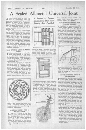
AUNIVERSAL joint in which the drive is transmitted, and the deflection accommodated by a metal bellows is shown by P. Thornhill, Henry's. Cottage, Harbury, Warwickshire, in patent No. 564,963. The joint can be completely sealed so as to retain lubricant for the whole of its working life.
The drawing shows a joint suitable for the propeller shaft of a road vehicle. The flange (1) bolts-on to the gearbox output shaft, whilst the tubular propeller shaft (2) may be permanently attached by welding. A central balland-socket (3) maintains concentricity, but this may be omitted if a stronger bellows be used. The bellows unit is built up by brazing together a series of S-section discs, overlapping portions being provided on the maximum and minimum diameters.
LEAF SPRINGS USED IN WHEEL DESIGN
'THE present shortage of rubber has 1 given fresh impetus to the search for a self-resilient wbeel, and patent No. 564,901 shows a design for a corn2 ponent of this type. The patentee is F. Gibson, Buccleuch, Pretoria Road, Johannesburg, S.A.
This inventor proposes to unite the rim of the wheel to the hub, through the intermediary of a number of leaf springs of conventional pattern. The thinly rubbered rim has the springs bolted to it, whilst the inner ends are shackled to radial projections on the hub. To prevent the entry Of dirt, both rim and hub are fitted with overlapping discs which can slide over each other, a soft packing ring being interposed. For heavy vehicles; it is proposed to employ two sets of springs in staggered relationship.
UNUSUAL DESIGN FOR A ROTARY VALVE
A ROTARY VALVE of the sleeve CIL type forms the subject of patent No. 564,886, from G. A. and R. Davies, all of Mill House, Kempston, Beds. The valve is intended to be located in the centre of the cylinder of a horizontal opposed-piston engine.
The drawing shows the centre a:14 portion of such a cylinder, in whicl the pistons reciprocate in a. sleeve (1 which, itself, is made to rotate. The Central, solid portion (2) is cut away to receive the valve (3); this consists of a part-circular piece which is pressed into contact with the cylinder wall by a combination ot springs and the developed pressure. The quadruple port (4) is actually a single slot, a crosssection of which resembles the letter W. The slot uncovers successively the inlet port, a sparking plug or injector bore, and the exhaust outlet. The engine itself forms the subject of another patent, No. 564,967.
DUAL-PURPOSE BUMPER FOR TRACTOR WINCHES
AN addition to tractors, as modified for timber haulage, is shown in patent No. 564,813, by Stanhay (Sevenoaks), Ltd., J. Cleland and W. Wilkins, all of The Vine, Sevenoaks. The aim is to strengthen the front of the machine so that it can penetrate undergrowth and other obstacles and, at the same time, to provide a counterbalance to hold the nose down when the winch is performing heavy haulage. To this end, .a heavy channel-section curved bar (1) is joined to a grille (2) to form a rigid
protection at the front. The weight for the counterbalance is provided by a solid metal block (3), which can be either a casting or a sheet-metal box filled with lead.
MOVABLE TUYERE FOR GAS GENERATORS
DATENT No. 564,704 comes from K.
Kane, Saffle, Sweden, and discloses an improved adjustable tuyere for use with gas producers, particularly of the charcoal-burning variety. The aim is to increase or decrease the size of the fire in accordance with the demand for gas and, at the same time, to reduce the risk of the fuel bed becoming choked with ash.
In this scheme, the air inlet and the gas outlet are concentrically located, and the composite tube thus formed can be moved in or out of the body. The air-inlet (1) is a straight-through tube leading into the fire zone, whilst the generated gas is drawn from the fire, via a grating (2) on the end of a second or gas tube, and makes its exit from pipe 3.
The varying demand of the engine creates suction in the outlet, and this affects diaphragms 4 and 5 connected to the two tubes. In operation, an increased suction causes the gas tube to be pushed farther into the fire, and the air tube even farther, thus enlarging the fire zone. The grating is claimed not to choke, owing to its high temperature and the continual movement, which cause the ash to be broken into small particles to be carried away with the gas stream.