


MAKING THE TYRES FUNCTION AS SPRINGS.
Page 12
Page 13
If you've noticed an error in this article please click here to report it so we can fix it.
Details of an Extraordinary System of Springing in which the Load of the Vehicle is Borne on the Upper Surfaces of its Pneumatic Tyres.
METE NUMBER of inventions dealing with the spring-1. ing of motor vehicles is naturally considerable, but it is seldom that so revolutionary a system has been devised as that provisionally protected by Mr. W. S. Boult, A.M.I.C.E., 6, Quality Court, Chancery Lane, London, E.C.2.
Hitherto, Mr. Boult believes, pneumatic-tyred wheels have always been loaded through their axles, thus there is only one thickness of tyre between the load and the road, and, consequently, supplementary springs, usually of the laminated type, have had to be employed, except
in a very few machines, such as the Fordson tractor, where no springs are utilized for the rear axle.
Mr. Houk considers that the ordinary forms of metal spring are by no means satisfactory, and he set about so to arrange matters that two, three, or even four, thicknesses of tyre in series could come into play between the load and the road.
To this end he has developed a number of designs in all of which the tyres are loaded through the medium of wheels or rollers resting on the upper parts of the tyre peripheries. With this system the wheels need not be joined by an axle; they can, if required, be carried by some form of stub axle, suitably linked to the chassis so that free up-and-down movement is allowed within the limits permitted by the flexion of the tyres.
In the most simple case a group of non-resilient rollers or a single non-resilient wheel can rest directly on each tyre; then it will be seen thartwo thicknesses of such tyre act in series as road shock absorbers. If, instead of non-resilient rollers or wheels, a pneumatic-tyred wheel be interposed, then it is apparent that there will be three thicknesses of the tyre in series, each capable of absorbing a certain amount of shock.
Other ways of obtaining the equivalent of three thicknesses of tyre without the use of an overhead resilient wheel have also been devised, and when tandem pairs of road wheels are employed, as in the case of a semibogie six or eight-wheeled vehicle, the total tyre flexion afforded is equivalent to that given by a series of four thicknesses.
Mr. Boult suggests that no shock absorbers will be wanted, as their purpose is simply to prevent the springs from rebounding beyond their normal position, but pneumatic tyres can only do this to a most minute extent.
In many Of the designs the differential is rigidly held in the chassis in fixed relation to the gearbox. In these cases, plain propeller shafts may take the place of the cardan shafts, and a considerable amount of the weight Is then sprung.
One suggestion is that the load-bearing rollers or a26
wheels can also act as driving members, several being connected together by belts resting on the peripheries of the wheels and driving the wheels through friction.
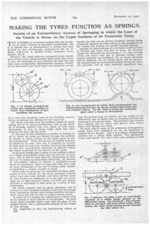
Against the disadvantage of a probable small increase of friction and wear and tear on tyres, the inventor claims the following six advantages :—(1) Leaf springs which are heavy and apt to rebound beyond their normal positions are abolished; (2) no shock absorbers will be required ; (3) no cardan shaft will be wanted; (4) humps could be surmounted without lifting the load ; (5) pot-holes will be more smoothly negotiated than with the present type of vehicle; (6) the weight of the differential and its shafts may be transferred from the unsprung to the sprung load. The inventor also expects that running will be easier and quieter than where heavy leaf springs are used. To show clearly some of the numerous arrangements which have been submitted 'VI us, we reproduce a number of the designs. Fig. 1 is a simple arrangement suitable for a cheap, light vehicle. The pneumatictyred road. wheels (A) have their axles guided in horn plates so that the play may be more in line with the direction in which jolts are received than if they were mounted vertically. The weight of the vehicle is applied to the wheels (A) by a pair of pneumatic-tyred wheels (C), driven directly by the differential shafts, which are held rigidly in position on the chassis, but, of course, allowed to rotate ; the drive between these wheels is by friction. It will be seen that in this design three thicknesses of tyre come into play.
Fig. 2 shows how three compressions in series may be obtained from one tyre by applying the load through a bell-crank lever, or, preferably, a pair of bell-crank levers, and non-resilient rollers (C). The tyre of the road wheel (A) which may be driven in any suitable manner, is shown surmounting a 9-in, hump in the road without raising the load, through the fact that the total compression is split between throe or four thicknesses of tyre acted upon through the medium of the hell-crank or cranks. It will be noted that when two bell-cranks are used at each side of the road wheel, each crank transmits only half the load at that side of the vehicle, or a quarter of the full load at the rear end.
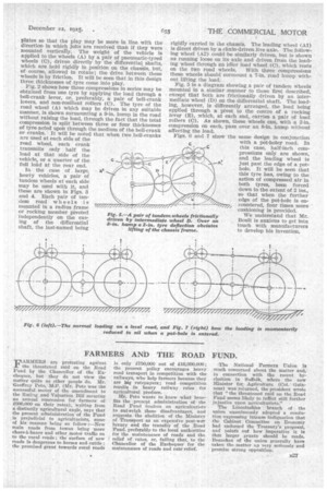
In the case of large, heavy vehicles, a pair of tandem wheels at each side may be used with it, and these are shown in Figs. 3 and 4. Each pair of tandem road wheels is mounted in a radius frame or rocking member pivoted independently on the casing of the differential shaft, the last-named being
rigidly carried in the chassis. The leading wheel (Al) is direct driven by a chain-driven live axle. The following wheel (A2) could be similarly driven, but is shown as running loose on its axle and driven from the leading wheel through an idler load wheel (C), which rests on the two road wheels. With three compressions these wheels should surmount a 7-in, road hump without lifting the load.
Fig. 5 is a diagram showing a pair of tandem Wheels mounted in a similar manner to those first described, except that both are frictionally driven by an intermediate wheel (D) on the differential shaft. The loading, however, is differently arranged, the load being applied through a pivot to the centre of a rocking lever (E), which, at each end, carries a pair of load rollers (C). As shown, these wheels can, with a 2-in, compression on each, pass over an hump without affecting the load.
Figs. 6 and 7 show the same design in conjunction with a pot-holey road. In this case, half-inch compressions only are shown, and the leading wheel is just past the edge of a pothole. It will be seen that this tyre has, owing to the action of compressed air in both tyres, been forced down to the extent of 2 ins., so that when the further edge of the pot-hole is encountered, four times more cushioning is provided.
We understand that Mr. Boult is anxious to get into touch with manufacturers to develop his invention.