


THE HARMONY OF DESIGN.
Page 9
Page 10
If you've noticed an error in this article please click here to report it so we can fix it.
Points Which Some Designers Overlook. By "Engineer-Designer."
IN THE design of a complete motor vehicle there is more in the harmony of design than is recognized by some designers. A given diameter of rear axle may carry a certain load well in conjunction with certain springs, but transplant that same axle into a chassis fitted with less flexible springs and it will not be found to be strong enough.
In the same manner the parts designed to work in conjunction with an epicyclic gear on a well-known American model have been found wanting when e rtbodied in a design in which an ordinary clutch is used—the ordinary forms of clutch being more sudden in action than the band applied to the epicyclic gesr. The same principle applies ta I component parts as well as to tha whole arrangement.
As an instance, one may see what appears to be a very slender stub axle for a front wheel. It may seein ridiculously light for the load it has to carry. Such a stub axle may give every satisfaction when used in conjunction with an equally light main front axle, but should an unlucky designer copy the dimensionsof such a stub and use them with a less flexible main axle he will, in
• all probability, have cause to regret it.
When some part of the mechanism of a motor vehicle breaks it is not always the fault of that; individual part being too weak. It may be, and often is, caused,by
. some other part° being too strong. The following illustrations of this principle are intended to draw the attention of deeigners to the importance of always bearing in mind the relative strength of one part to another.
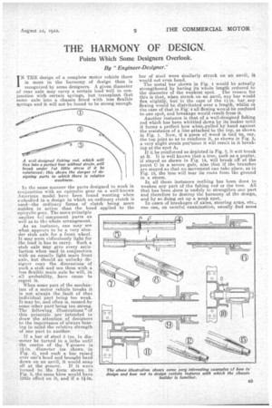
If a bar of steel 3 ins. in diameter be turned in a lathe until the centre of the V-groove is 1i-in. diameter (as shown in Fig. 4), and :such a bar raised over one's head and brought hard down on an anvil, it would snap
off at the groove. If it were tented to the form shown in Fig. 5, the same blow would have little effect on it, and if a 1i-in.
bar of steel were similarly struck On an anvil, it would not even bend.
The metal bar shown in Fig. 4 would be actually strengthened by having its whole length reduced to the diameter of the weakest spot. The reason for this is that, when struck on an anvil, any bar would flex slightly, but in the case of the 11-in. bar. any flexing would be distributed over a length, whilst in the case of that in Fig:4 all flexing would-be confined to.one spot, and breakage would result from it. Another instance is that of a well-designed fishing rod which has been whittled down by its maker until it forms a perfect bow when.pulled by hand against the resistance of a line attached to the top, as shown in Fig. 1. Now, if a piece of. wood is tied to, say, the top joint So as to reinforce it, as shown in Fig. '2, a very slight strain put'unon it will result in it breaking at the snot A.4 If it be reinforced as depicted in Fig. 3, it will break at B. It is well known that a tree such as a poplar, if stayed as shown in Fig. 14, will break off at the point C in a severe gale, also that if the branches are stayed so that no movement can take place, as in Fig. 15, the tree will tear its roots from the ground in a storm.
In all these instances nothing has been done to weaken any part of the fishing rod or the tree. All that has been done is unduly to strengthen one part and therefore to destroy the harmony of the design, and by so doing set up a weak spot. • In cases of breakages of axles, steering arms, etc., one can, on careful examination, usually find some
weak spot in the design which is the cause of the fracture. Sharp corners, abrupt ends of k,eyways, etc., are the usual causes of trouble. With a little care these can generally be avoided. A few instances tan be given where the trouble of repeated breakage has been remedied by re-designing on the lines indicated. A fan spindle in a certain design of vehicle gave trouble by breaking at the point D (Fig. 10) through "fatigue " in the steel caused by vibration. So high was the percentage of breakages that the company producing the machine had to take up the matter. It was dealt with as shown in Fig. 11, and after this there was not a single case of failure.
Collars formed integral with axles (Fig. 9) have been replaced with those designed as shown in Fig. 6, with equally satisfactory results. Squares as in Fig. 7 and keyways as in Fig. 12 have been replaced by those shown in Figs. 8 and 13 respectively, with good results.
It may be said that all this is well known to designers of motors ; that is so, or should be so, yet in spite of this one sees, even in the latest designs, items where the points mentioned above have been entirely disregarded.
Another point which should not be overlooked by designers is the danger of copying any device or dimension without assuring himself that the model he is copying is fully successful. In a business like that of motor construction a certain amount of copying is absolutely necessary and is not looked upon as plagiarism, but as a necessary step towards perfection.
The designer should, however, before copying any device or dimensions from the designs of another corn-any, assure himself that the particular arrangement has completely fulfilled the purpose for which it was designed. There are many in 'stances in the history of motor design where a certain method of construction which promised well has, in use, turned out a failure, owing to some hidden defects which use alone revealed.
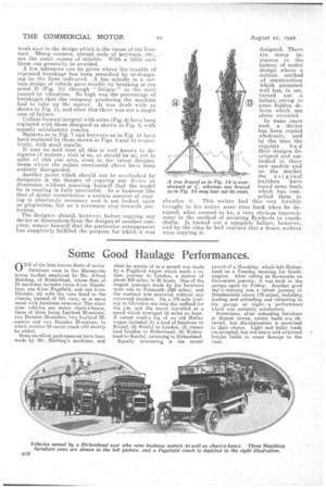
In some cases such a device has been copied wholesale, and by the time the copyists ha d their designs developed and embodied in their new models and on the market the original builders have found some fault which has corn polled them tc abandon it. This writer had this very forcibly brought to his notice some time back when he designed, what seemed to be, a very obvious improvement in the method of securing flywheels to crankshafts. It turned out a complete failure, however, and by the time he had realized this a dozen makers were copying it. A tree braced as in Fig. 14 is overstressed at C, whereas one braced as in Fig. 15 may tear out its roots. A tree braced as in Fig. 14 is overstressed at C, whereas one braced as in Fig. 15 may tear out its roots.