


Patents Completed.
Page 22
If you've noticed an error in this article please click here to report it so we can fix it.
PLATE CLUTCH MECHANISM.Royce—No. 16,388, dated 20th July, 1906. —In order to bring the driven portion of the plate clutch to rest when the plates are disengaged, a drum (1) which carries the driven plates (14) has two bosses (2, 2) formed in it, in each of which a bush (3) is fitted. These bushes (3, 3) carry pins (4, 5), one of which is fixed in a knuckle joint (6). The other pin (5) runs in a jaw (7) formed on the end of a driven shaft (8). On one end of a tube (9) is a metal disc (10) carrying a ring (11). The other end of the tube (9) has sliding keys (15) cut on it which fit into key-ways cut on the inside of the extension drum (1). On one side of the metal disc (10) two stationary rubbers (12), which act as brakes, are fixed. On the other side is a trunnion (13) which is actuated by the lever for disengaging the clutch plates (14). When the plates (14) are disengaged, the trunnion (13) is pressed against the ring (11) which is attached to the disc (10). The driven shaft (8) and the plates (14) are thus brought to rest.
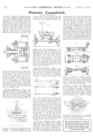
MOTOR VEHICLES. — Alley. — No. 25,364, dated 10th November, 1906.—This invention relates to steam-propelled vehicles of the front-driven and front-steering type in which the motor driving mechanism and the front road wheels are carried upon a perch frame beneath the fore end capable vehicle.
of the vehicle, which frame is of turning relatively to the A. motor (A) is adjustable longi
tudinally upon the perch frame (B) with its crankshaft (C) towards the forward end. Within the crank chamber, beneath, and parallel with, the crankshaft (C), and driven by spur gearing therefrom, is a differential gear (D). The brackets (F) and shaft (E) are of such a length that the chain wheels (G, 11) are in line with the chain wheels (J, K) ; these latter are carried in the usual manner. The perch frame (B) is moved relatively to the main frame (W), for steering purposes, by a worm wheel (X) fixed to the frame (B), with which a worm wheel (Y) gears. This latter is operated by gearing from the usual steering wheel (Z).
ANTI-SLIP DEVICE. — Iron. — No. 25,069, dated 7th November, 1906,—At the rear of the vehicle, two auxiliary wheels (1 are mounted. These are covered with coir yarn for the purpose of obtaining a grip upon the road ; they are carried by an axle (f) mounted in movable eccen tries. The eccentrics are provided with crank arms, each of which is connected by a link (5) with art operating pedal (d). When the pedal is depressed, the eccentrics are moved in such direction as to depress the wheels, and when these come into contact with the road, the forward movement of the vehicle aids the movement of the eccentrics for bringing the wheels into operation. Arms (h) are carried on the axle (f) and these turn with the eccentrics so that they are brought beneath lugs (1) on the frame of the vehicle when the wheels (e) are made to bear upon the road surface ; the weight of the rear portion of the vehicle is thus brought directly upon the axle (f).
ELECTRIC MOTOR.—United States Motor Vehicle Company.—No. 18,975, dated 24th August, 1906.—In this vehicle, each of the road wheels is provided with an electric motor, and constitutes an independent driving system. The motor of each wheel is mounted in casings (18, 19), and these casings are mounted on the ends of fixed axles (5, 6), The ends of the axles are jawed, and each limb of the jaw carries a trunnion (16) that enters the casing whereby the latter is secured in place. The front wheels, with their motor casings, are allowed to pivot on the trunnions, but the casings of the rear wheels are rigidly secured relatively to their connecting axles. The frame (1) of the vehicle is carried by springs (7, 8) that rest upon the axles (5, 6), and the connection between the springs and axles is such that the axles can move to a limited extent in the longitudinal direction of the vehicle. This movement prevents shocks imparted to the wheel in the longitudinal direction from being communicated direct to the frame, and the amount of movement per mitted is limited by spring-controlled buffer-members (10, 11). Suitable brake mechanism is provided for the rear wheels 114), and the front wheels are steered by means of links (26) connected by suitable means to the steering pillar (47).
BRAKE. — Keene. — No. 4,881, dated 28th February, 1907.—The brake-blocks 1c) are carried on the ends of rams (d). The rams slide in cylinders (e) disposed on opposite sides of a sleeve (el) secured to the axle of the vehicle. Fluid, admitted under pressure to the cylinders, applies the brakes against the action of a spring
(h), and an adjustable stop is provided to limit the return movement of the blocks under the action of the spring.