


Positive Closing of Engine Valves
Page 60
If you've noticed an error in this article please click here to report it so we can fix it.
the diameter of the bore should not exceed 0.035 in. in any circumstances.
A " MIDDLE-COMPRESSION " ENGINE
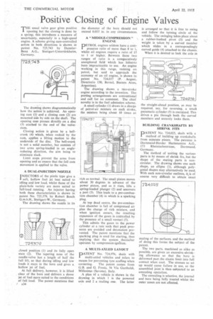
THE usual valve gear gives positive Opening but the closing is done by a spring; this introduces a measure of uncertainty, especially in a high-speed engine. A scheme giving cam-controlled action in both directions is shown in patent No. 725,743 by DaimlerBenz A.G., Stuttgart-Unterttirkheim, Germany.
The drawing shows diagrammatically how the action is achieved. An opening cam (1) and a closing cam (2) are mounted side by side on the shaft. The opening cam presses directly on a disc (3) atached to the end of the valvestem.
Closing action is given by a beltcrank (4) which, when rocked by the cam, applies a lifting motion to the underside of the disc. The bell-crank is not a solid member, but consists of two arms spring-loaded in an anglereducing direction, the aim being to eliminate slack.
Limit stops prevent the arms from opening and so ensure that the full cam movement is applied to the valve.
A DUAL-INJECTION NOZZLE
INJECTORS of the pintle type give a I soft, hollow fuel jet best suited to idling and low load, whilst those of the plain-hole variety are more suited to full-load running. An injector having both these characteristics is shown in patent No. 725,379, by Robert Bosch G.m.b.H., Stuttgart-W., Germany.
The drawing shows the nozzle in its closed position (1) and its fully open state (2). The tapering nose of the needle-valve has a length of half the full lift, so that during idling and low loads it stays in the bore and gives a hollow jet of fuel.
At full delivery, however, it is lifted clear of the bore and delivers a dense jet of fuel more suited to the conditions of full load. The patent mentions that / x34
PETROL engines seldom have a compression ratio of more than 8 to 1, whilst oil engines require a ratio of 15 to 1 or higher. Between these two ranges of ratio is a comparatively unexplored field which has hitherto been impracticable to use. An engine working in this range, running on petrol, but said to approach the economy of an oil engine, is shown in patent No. 724,037 (P. August, Directorio 130, Bernal, Buenos Aires, Argentina).
The drawing shows a two-stroke • engine according to the invention. The porting arrangements are conventional and call for no comment. The chief novelty is in the fuel admission scheme.
A small cylinder (1) draws in a charge of petrol-air mixture on each stroke, the mixture being about 10 times as rich as normal. The small piston moves about 30 degrees in advance of the power piston, and as it rises, lifts a spring-loaded plunger (2) and uncovers a port (3). This leads to a pre-combustion chamber (4) in which is a sparking plug.
At top dead centre, the pre-combustion chamber is full of compressed air plus the charge of rich mixture, and when ignition occurs, the resulting expansion of the gases is controlled by the presence of a small venturi (5).
This admits the gases to the power cylinder at a rate such that peak pressures are avoided and detonation prevented. The patent mentions that the sparking plug is used for starting, thus implying that the system thereafter operates by compression-ignition.
A MULTI-AXLED LAYOUT
PATENT No. 724,976, deals with multi-axled vehicles and refers to means for preventing tyre scuffing when
cornering. The patent comes from G.B. and G. Fresia, 56 Via Garibaldi, Millesimo (Savona), Italy.
A plan of a vehicle is shown in the drawing in which 1 is the powered axle and 2 a trailing one. The latter
is arranged so that it is free to swing and follow the turning circle of the vehicle. The swinging takes place about a rubber-bushed pivot (3) and the weight is taken by a curved member which slides in a correspondingly curved guide (4) attached to the chassis.
When it is desired to lock the axle in BUILDING .CRANKSHAFTS BY SHRINK FITS
PATENT No. 724,025, deals with a method of building up crankshafts from separate pieces. The patentee is Dortmund-Horder Huttenunion A.G., 173 Rheinischestrasse, Dortmund, Germany.
The method of uniting the various parts is by means of shrink fits, but the shape of the mating parts is noncircular. The drawing shows one such shape, an ellipse (1), although polygonal shapes may alternatively be used. With such non-circular outlines, icis of course very difficult to obtain exact mating of the surfaces, and the method of doing this forms the subject of the patent.
The two parts, machined as alike as possible, are given an excessive -shrinking allowance so that the bore is deformed past the elastic limit into full contact when cool. The stresses so set up would cause failure in use, so the assembled joint is then subjected to an annealing operation.
The annealing is selective, the journal and bore being fully treated whilst the outer zones are not affected.