


Torque Converter With Anti-creep Brake
Page 26
If you've noticed an error in this article please click here to report it so we can fix it.
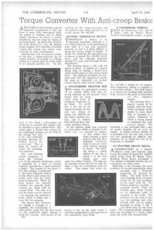
A FEATURE of the Fottinger type of (t hydraulic transmission is that the drive is never fully interrupted while the engineis running, and at idling speeds, therefore, the driver is recommended to stop the creep by means of the hand brake. In patent No. 614,551, the Ford Motor Co.. Ltd., 88, Regent Street, London, W.1, describes a braking system that comes into action automatically in such circumstances.
Dealing first with the general outline of the unit, a torque-converter has its output member (I) carried on a flange splined to a central shaft (2) which leads
to an epicyclic gearbox (3). On this
shaft is also .fixed a clutch-plate (4) which can be pressed into contact with the flywheel to give a direct drive. The clutch plate is forced into contact by the centrifugal pressure iof the fluid in the casing,':., but only
if the same • hydraulic pressure between the
• friction f ace s• We •reIieve.d This is done by valves (5) which are centrifugally operated.
The auto braking system comprises a drum I (6), forming part of the epic.yclic mechanism, which is encircled by a band of friction material, operated by a small hydraulic cylinder.The essence of the patent is that this cylinder is connected to the main hydraulic brakes on the Wheels; and comes into action eve?y time the brake pedal is depressed. When the main brakes are released, however, the epicyclic brake remains on, being held by trapped fluid. The 'only way that this brake can be released is by pressing the accelerator pedal, which is fitted with a valve for, this purpose.
This .means that whenever the vehicle is brought to a standstill, the transmission is held :against creep; but the first touch on the accelerator pedal releases it ready for running. Full details of the n>2 working of the torque-converter and the gearbox have been covered by an earlier patent, No. 602,020.
BATT'ERY TOPPING-UP DEVICE TOPPING-UP a battery is an / important operation, although it is one which often has to be performed in poor light in a not very accessible position, so that it is often difficult to gauge the correct height of liquid. A device for rendering the operation'easy is shown in patent No. 611,395, by R. Gray, and the Chloride • Electrical Storage Co., Ltd., both of Exide Works, Manchester.
The drawing shows a cell with the device in place. It consists of a special filling plug (1) having a flared bore Which reaches down to the correct liquid level.The addition ofliquid can continue only until the rising level reaches the plug as, thereafter, . an air-lock occurs, and no more can be added.
A TWO-PURPOSE TRACTOR RIM THE wheels of agricultural tractors 2. arc ustrally fitted with lugs for giving adhesion on soft ground, which means that for road work some form of temporary band has to be fitted. To avoid this is the aim of an improved design of rim and tyre shown in patent No. 609,473 by the Andre Rubber Co., Ltd., and T. Gillett, both of Hook Rise, Tolworth, Surbiton, Surrey.
In this scheme, spade lugs,' attached to a base plate which is secured to the Wheel . rim, are encased in rubber, so that whilst their shapeensures a good grip on soft soil, -their resilience enables them to run on a hard road witWout damage or shock. The drawing shOws a typical sectionof the tug in which I is the rim
bolted steel . core, and 2 the rubber overlay. The lugs are set -helically across the rim so that the effect is that of a continuous circle of rubber. This means that when the
A CHASSISLESS VEHICLE
FR.0111 the Rover Co., Ltd., and M Wilks, both of Meteor Works Solihull, Birmingham, comes, in paten No. 613,784. a design for an indepei. dent suspension scheme as applied tc chassisless vehicle. The chief featurc is a means for avoiding high localized body stresses at the point of attachment of the suspensior system.
The drawing gives a general' outline. of thL vehicle, with the frontwheel springing systen• shown in more detail. This is attached to a vertical bulkhead (I) which is strong enough to withstand the road wheel shocks. --Chi-, bulkhead is also provided With a pail: of sturdy brackets (2) to carry the -engine.A similar vertical member (3) is 'provided over the rear axle, and the two are connected by edge-on sidemembers (4) to which the rest of th.2. bodywork is attached.
AN ELECTRIC CRANE TRUCK
A COMBINATION of a batteryPt electric crane and fork-lift truck forms the subject of patent No. 614,445, which comes from W. Boase, Tower Building, Water Street, Liverpool, 3. The scheme is intended mainly, but not exclusively, for dock work.
Refefring to the drawing, the crane portion is of normal construction, being provided with a forwardly projecting jib pivoted for luffing. The cable from the main hoisting drum (1) passes round the jib and terminates in the usual hook (2). The forked platform assembly is operated directly from the hoisting gear, being worked by an additional cable (3) attached to the • hook. The platform can' be used in that way for stacking, and, when finished with, can be rapidly detached at points 4 and 5.
and lifted away by the crane itself. The increased length attendant upon the mounting of a crane, might make the outfit less marweuvrable.