


A NEW 2-21-TON ELECTRIC VEHICLE.
Page 42
Page 43
If you've noticed an error in this article please click here to report it so we can fix it.
A New Electric Truck in which a Direct Drive from the Motor is Taken to a Worm-driven Rear Axle.
D'
'STONED primarily to compete
with the horse in city congestion and to de away, as far as Possible, with slow-moving traffic, the General Vehicle Co., Ltd., of TyseleY,. Birmingham, in their new 2-24-tow chassis have further improved upon their already successful electric vehicles and have enlarged generally the load capacity. Au innovation so far as this company is concerned is the inclusion of a direct drive from the eleetric_motor_tq a worm-driven rear axle, which' has provided a much quieter and sweeter drive than the chains previously used.
The main .frame consists of two steel channels running fore and aft and suitably braced with cross-members • of channel section, bolted to the main frame in substantial and robust caststeel brackets. Actually, there are five channel cross-members-located at various points throughout the length of the fraine and one tubular member right at the front; thus a very stiff structure is obtained. All the units, such as the motor, battery cradles, steering gear, controller and, of course, front and rear axles, are mounted in such a manner that any of them can be removed for adjustment, repair or cleaning, without interfering with any other part—all points, of course, which are a great consideration from the maintenance point Of view.
Turning now to the description in detail, the series-wound S5-volt motor is slung on a bar in the centre-line of the chassis, between two cross-members, on which trunnion mountings are arranged, so that when the caps are removed, the motor, complete with its bar, can be taken out. There is a torque arm running tangentially from the inner part of the off-side frame member to a point on the motor casing. The casing completely encloses the whole of the working parts of the motor, thus preventing any possibility of failure occurring through moisture causing a short circuit. There is, however, an inspection door on the front cover, through which access can be gained to the commutator
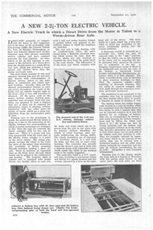
and brushes. The propeller shaft is tubular and is equipped with double Hardy disc flexible joints at each end,,
with a ball and socket location formed in spiders bolted and spigoted to the ordinary spiders to which the couplings are attached.
The rear axle is fully floating, with an overhead-worm drive, the main casing being a Kirkstall one-piece forging which carries the load; thus the driving shafts are onlyrequired to transmit the drive from the worm wheel to the road wheels. The differential is of the bevel type which, complete with the worm and worm wheel, can be removed from the axle in one piece with its housing without disturbing the wheels or wheel bearings, after partially withdrawing the driving shafts. The wheels themselves are of cast-steel in a cruciform section, in a unit with the hubs, and they run on taper roller bearings. The controller box actually forms the driver's seat and is built into a skeleton frame with removable covers, which enable the whole of the working parts to be readily inspected.
The controller itself is a G.V. standard type, providing a continuous torque and having five speeds forward and two reverse, operated by a lever on the right
hand side of the driver. The lever
.1vorks in a gate, which has a stop provided to avoid any possibility of the driver accidentally getting into the reverse positions.
A three-way switch is operated by a removable key, which can only be removed when in the " safe " position, so that the vehicle can be left standing in the street and by removing the key be protected from operation by anyone not in possession of the key. A Sangamo ampere-hour meter is fitted to the dashboard and records the state of the battery, a trip-switch circuit breaker automatically disconnecting the battery when it is fully charged. The whole controller-drum unit is mounted in plain trunnion bearings, so that, when the segments require either replacing or thorough cleaning, they can easily he removed complete with their shaft through the inspection coverplate previously mentioned.
The resistance is not contained in the controller box, but is located beneath the floor boards, where there is usually a draught to assist in keeping it cool.
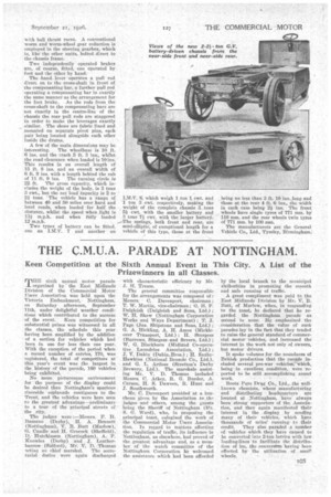
The battery boxes are rather ingeniouslY housed in a pair of cradles, which are suspended from the 'chassis frame by four hooks in such a manner that they can be removed complete in a very few minutes for an exchange of battery. This can be accomplished by placing a jack truck beneath the battery compartment. and by lifting the whole unit about in.; the hooks can then be swung upwards and the battery and casing complete lowered on to the truck. The batteries themselves are contained in four roller trays, two on each side of the vehicle, each tray carrying 11 cells. They are normally enclosed by inspection doors, which on the removal of two spring clips can be lowered into a horizontal position and the roller trays drawn outwards for inspection and topping up without necessitating the use of tools. Altogether a very ingenious arrangement.
Turning now to the chassis details, the front axle is a forging of H-section, with the spring pads formed on the upper part ; the stub axles are fitted with ball thrust races. A conventional worm and worm-wheel gear reduction is employed in the steering gearbox, which is, like: the other units, bolted direct to the chassis frame.
Two independently operated brakes are, of course, fitted, one operated by foot and the other by hand.
The .hand lever operates a pull rod direct on to the cross-shaft in front of thu compensating bar, a further pull rod operating a compensating bar in exactly the same manner as the arrangement for the foot brake. As the rods from the cross-shaft to the compensating bars are not exactly in the centre-line of the chassis the rear pull rods are staggered in order to make the leverages exactly similar. The shoes are fabric lined and mounted on separate pivot pins, each pair being located alongside each other inside the drums.
A few of the main dimensions may be interesting. The wheelbase is 10 ft. 6 ins, and the track 5 ft. 3 ins., whilst the road clearance when loaded is 10 ins. This results in an overall length of 15 ft. 8 ins. and an overall width of 6 ft. 9 ins, with a length behind the cab of 11 ft. 9 ins. The turning circle is 22 ft. The gross capacity, which includes the weight of the body, is 3 tons 3 r
cwt, but the net load capacity is 2 to 211.r tons. ' The vehicle has a range of between 40 and 50 miles over hard and level roads, when loaded for half the distance, whilst the speed when light is 13mph. and when fffily loaded 12 m.p.h.
Two types of battery can be fitted, one an 1.htS. 7 and another an I.M.V. 8, which weigh 1 ton 1 cwt. and 1 ton 3 cwt. respectively, making the weight of the complete chassis .3 ...ton 5i cwt. with the smaller battery and 3 tons V ewt. with the larger battery.
springs, both front and rear, are semi-elliptic, of exceptional length for a vehicle of this type, those at the front being no less than 3 ft. 10 ins. .long and those at the rear 4 ft. 6 ins., the width in each ease being 2Ains. The front wheels have single tyres of 771 min. by 110 mm. and the rear wheels twin tyres
of 771 ono. by 100 mm. • The manufacturers are the General Vehicle Co., Ltd., Tyseley, Birmingham;