


Feeding Arrangements for Pulverized Fuel
Page 62
If you've noticed an error in this article please click here to report it so we can fix it.
fiANY experiments have been made 1V lin Germany with the object of using powdered coal-dust as a fuel for internalcombustion engines. With such a fuel the method of feeding it to the engine presents many problems, and patent No. 491.832 discloses a recent development. The patentee is the Hanomag concern, of 1, Hamelnerstrasse, Haniaover-Linden.
In the drawing, air at low pressure arrives via pipe 6 and passes under an adjustable restriction (5),. Beyond this, fuel-dust from pipe 1 meets the air stream andmingles therewith and the mixture is carried into a spherical chamber (3), in which it is maintained in a continuous state of whirl. The timed admission valve (2) controls the actual cylinder charge, which issues from the nozzle (4) and accompanies the main air stream into the cylinder.
An Internally Cooled Piston.
...THERE is a distinct trend in piston I design towards the incorporation of a self-contained cooling-fluid circuit; such a design is described in patent No. 491,843, by A. Nicolle and the Automotive Engineering Co., Ltd., 104, The Green, Twickenham The piston shown in the accompanying drawing comprises a steel skirt and ringcarrying portion and a welded-in head with a central boss (1). The gudgeonpin bosses are bridged by an 1-section arch (a), which contacts with the hods on the crown. A sheet-metal liner (2) closes off a part of the interior, extending down to the bottom of the skirt. The space so formed is filled with either sodium or a readily fusible salt.
Improvements in Piston Rings.
DESIGNS for both compressionretaining and oil-scraping piston rings are disclosed in patent No. 491,262, by A. Wenzel, 1, Ridgeway Avenue, West Orange, New Jersey, U.S.A. In addition to the foregoing properties, the rings are intended also to ensure adequate lubrication on their piston-engaging surfaces.
A36 The drawing shows a section of a pair of each type, those in the upper groove being compression rings, whilst the oil scrapers are housed in the lower groove. The compression rings have a Vshaped groove I), the lower half of which traps oil and feeds it to an innner, concentric groove (2), the function of which is to distribute the oil evenly around the rings for internal lubrication. The scraper rings also have this groove, but, in this case, the oil is led to return holes drilled in the piston. 4 91,a 62.
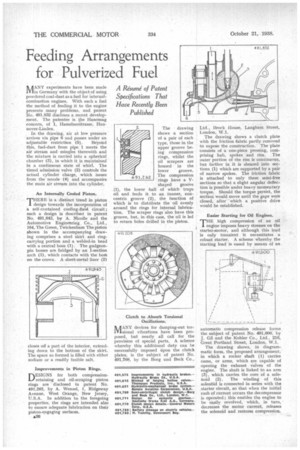
Clutch to Absorb Torsional Oscillations.
ANY devices for damping-out tor1Visional vibrations have been proposed, but nearly all call for the provision of special parts. A scheme whereby this additional duty can be successfully imposed upon the clutch plates, is the subject of patent No. 491,708, by the Borg and Beck Co.,
Ltd., Brock House, Lan gharn Street, London, W .1.
The drawing shows a clutch plate with the friction fabric partly removed to expose the construction. The plate consists of a one-piece pressing, comprising hub, spokes and rim. The outer portion of the rim is continuous, but farther in it is sheared into sections (1) which are supported by a pair of narrow spokes. The friction fabric is attached to only these semi-free sections so that a slight angular deflection is possible under heavy momentary torque. Should the torque persist, the section would move until the gaps were closed, after which a positive drive would be established.
Easier Starting for Oil Engines.
THE high compression of an oil engine imposes heavy stresses on the starter-motor, and although this load is only transient it necessitates a robust starter. A scheme whereby the starting load is eased by means of an
automatic compression release forms the subject of patent No. 491,600, by J. Gil and the Kohler Co., Ltd., 216, Great Portland Street, London, W.1, The drawing shows, in diagrammatic form, the proposed arrangement, in which a rocker shaft (1) carries cams, or arms, which are capable of opening the exhaust valves of the engine. The shaft is linked to an arm (3), which carries the core of a solenoid (2). The winding of this solenOid is connected in series with the starter circuit, so that when the initial rush of current occurs the decompressor is operated; this enables the engine to be easily revolved, which, in turn, • decreases the motor current, releases the solenoid and restores compression,