


A Two-speed Gear and Fluid Flywheel
Page 66
If you've noticed an error in this article please click here to report it so we can fix it.
T Engineering of the Alvis Car and Co., Ltd. and G. T.
Smith-Clarke, numbered 3'79,973, relates to an interesting adaptation of the now well-known Ffittinger type of fluid flywheel, combined with a two-sliced gear of the epicyclic kind.
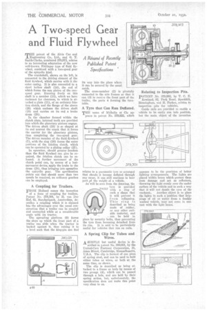
The crankshaft, shown on the left, is connected to the driving element of the fluid flywheel, which carries with it the outer casing. It is also connected to a short hollow shaft (14), the end of which forme the sun pinion of the twospeed gear. Running freely on this shaft is a member (13), which we have darkened for clearness, to which is attached a plate (11), of an ordinary friction clutch, and the flange of the sleeve (26) which encloses the driven shaft (18) and carries on its end a brake drum (28).
In the chamber formed within the clutch plate, internal teeth are provided into which the planetary pinions engage. The driven shaft (18) is so shaped at its end nearest the crank that it forms the carrier for the planetary pinions, thus completing the two-speed gear. The driven member of the fluid flywheel (7), with the ring (10) forms the outer portions of the friction clutch, which can he operated by a sliding collar (27).
In operation, should greater freedom than the fluid flywheel can give be required, the friction clutch can be released. A further movement of the clutch pedal can, by means of a lostmovement device, apply the brake to the drum (28), thus bringing into operation the epieyclie gear. The specification points out that should more than two speeds be required, an oidinary gearbox can be employed.
A Coupling for Trailers.
FROM Holland comes the invention
of a form of coupling for trailers. Patent No. 379,301, by H. van Der Hof, 61, Sarphatipark, Amsterdam, deseribes a coupling which it is claimed has the advantages over the usual construction that a trailer can be coupled and uncoupled while at a considerable angle with its tractor.
The spreading platform (9) forms the slope up which the front part of a trailer can slide when the tractor is backed against it, thus raising it to a level such that the king-pin can find its way into the place where it Can be secured by the usual catch.
The cross-member (2) is pivotally connected to the side frames so that it can tilt to receive the front part of the trailer, the parts 4 forming the turntable.
A Tyre that Can Run Deflated.
TEE name of MiChelin et Cie appears in patent No. 379,925, which
relates to a pneumatic lyre so arranged that should it become deflated through any cause, it can still continue to bear Part ipf the weight of a vehicle. As will be seen front the drawing, the tyre is provided with a ring of such a shape that it will prevent it f rem collapsing. This ring is described as being made of rubber, or any other suitable material, and can be held in place by security bolts, thus preventing the tyre from becoming detached from
its rim. It is said to be particularly useful for vehicles that run on rails.
A Spring Clip for Tubes and Wires.
A. SIMPLE, but useful device is de scribed in patent No. 380,031, by the United-Carr Fastener Corporation, 31, Ames Street, Cambridge, Massachusetts, -U.S.A. The clip is formed of one piece of spring steel, and can be used to hold either tubes or wires, or both at the same time, as shown.
The clip is described as being attached to a frame or body by means of two prongs (4), which can be passed through a hole, and are held by their spring action, but, unfortunately, the specification does not make this point very clear to us.
Relating to Inspection Pits.
PATENT No. 879,993, by T. C. E.. Rowland, 82, Park Road, Sparkhiil, Birmingham, and II. Parker, relates to inspection .pits for vehicles, Guide rails are provided to enable a vehicle to be easily run into position, but the main object of the invention appears to be the provision of better lighting arrangements. The lights are placed within boxes which protect them from damage and act as reflectors, throwing the light evenly over the under surface cif the vehicle and in such a way that it will not dazzle the eyes of the mechanic. Another object is to place the lights in each a position that drippings of oil or water from a freshly washed vehicle, may not come in contact with the light boxes.