


REAR-ENGINED Bus
Page 54
Page 55
If you've noticed an error in this article please click here to report it so we can fix it.
in America
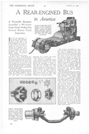
IN view of experiments in this country with passenger vehicles having power units mounted at the side of the frame amidships, it is of interest to learn that a favourable reception has been met with in America by a 40-seater rearengined single-deck bus, which, for some months, has been in Production by the General Motors Truck Corporation,. Pontiac, Michigan.
In this case the body frame and chassis form a single-girder construction, in which the engine-gearbox unit is mounted behind the rear whaels, the gearbox being before the engine. The wheels are carried on an arched dead axle, and the drive is conveyed to the wheel centres through Rzeppa constantvelocity wire' sal joints. Interesting features are the cooling system and the vacuum clutch control.
In the unit construction of the body and under-frame heat-treated aluminium alloys are largely employed, and a weight saving of 3,000 lb. is claimed. The side pillars are heat-treated aluminium drop forgings, the panels being of light alloy I in. thick.
The type-616 six-cylindered Petrol engine, which develops 150 b.h.p. at the governed speed of 2,100 r.p.m., is employed, this developing a torque -of about 440 ft.-lb. throughout the range from 600 rai.m. to 1,400 r.p.M. The engine, gearbox and final-drive unit arc mounted together in a light-metal subframe, and this assembly is held in position in the main framework by eight tapered dowels, two heavy bolts forcing the dowels into place. The assembly can be readily removed. • The clinch is controlled by a I-in. steel rod, this being in tension when the clutch is withdrawn. An automatic vacuum control is provided, which may or may not be used, at the will of the driver. Vacuum from the induction manifold operates a piston • connected to the auxiliary mechanism and is under the .control of a pedal, the depression of which disengages the clutch. Easy gear change is obtained, and the clutch is re-engaged merely • by pressing on the accelerator pedal. If -the driver removes his foot from the small pedal, the vacuum becomes inoperative, leaving the conventional clutch-pedal control.
The four-speed gearbox gives indirect ratios of 1.70, 2.86 and 4.27 forward and 4.76 reverse, control being by a single long aluminium tube, which passes under the floor. A spiral-bevel finaldrivegear is employed, the standard ratio .being 5.625 to 1, whilst optional ratios of 6.125' and 5.125 are available.
The dead axle is a seamless steel tube of enter diameter 4i ins, and inner -diameter 3i ins. End castings, „shrunk and riveted on, carry the Wheels, brake spiders and gearing, also • the brake-application diaphragms, and the drive passes through these castings, being transmitted from the shafts to the wheels through toothed couplings.. The drive is conveyed through Rzeppa ball-type constant-velocity universal joints, of which four are used, there being one at each end of each drive shaft. Each joint has six Win. steel balls and, in each case, the grooved spherical inner race is attached to the driving member. The balls thus operate within radial grooves.
This interesting constant-velocity coupling was first referred to in our issue dated November 3, 1931, and again mentioned in our issue dated September 23, 1932, in connection with the Gilford front-drive passenger vehicle, in which it is employed. In the G.M.C. bus the maximum angularity permitted is 7 degrees.
Both front and rear springs are of heat-treated alloy steel, 5 ft. 4 ins, long and 4 ins. wide. They are Jaf the semielliptic type and have removable bronze bushes. Internal-expanding air-operated service brakes are fitted to all wheels, two pairs of shoes in each drum being actuated by separate camshafts, and these, in turn, operated by Westinghouse double-acting air diaphragms mounted on the axle. The cast alloyiron drums are unusuallylarge, being 20 ins, in diameter and 4 ins, wide, and they give a service-brake friction area of 845 sq. ins. Two air reservoirs are provided, and are fed by a two-cylinder compressor mounted on the engine.
Additionally, emergency brakes are mounted on the rear drive shaft, alongside the final-drive unit. In this case, the drums are 16 ins. in diameter and 3 ins, wide, this brake being operated by a hand lever.
The standard tyre equipment is 9.75-in. by 24-in. low-pressure pneumatics, with twin rear tyres. The engine-cooling system, which is unusual, is claimed to be most efficient. The radiator is located in the left rear corner of the body, and a fan behind it draws air from the outside around the shrouded front end of the engine. This air passes into the ends of the shrouded exhaust manifold, and out of the coach through a venturi. The radiator has thermostatically controlled shutters. It is said that at 10 m.p.h. 300 cubic ft. of air are ejected per minute, and that at 40 m.p.h. the figure is 1,075 cubic ft.