


Constant-clearance Brake Adjustment
Page 72
If you've noticed an error in this article please click here to report it so we can fix it.
ADEVICE that automatically takes up wear in a disc brake is described in patent • No. 802,942. It operates by friction and is designed so that when adjusting it is easy to achieve the correct degree of clearance. (The Goodyear Tire and Rubber Company, Akron, Ohio, U.S.A.)
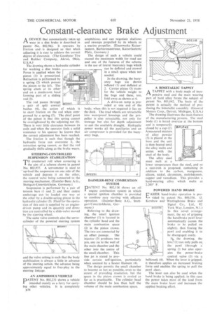
The drawing shows a hydraulic cylinder for working a disc brake Force is applied when the piston (1) is pressurized. Retraction is performed by a spring (2) which presses the piston to the left. The spring abuts at its other end on a mushroom head forming part of a sliding rod (3).
The rod passes through • a .pair of split• conical bushes .(4), the action of which is to exert friction on the rod when compressed by a spring (5). The chief point of the patent is that this spring cannot be overtightened by the adjusting nut (6). There is very little clearance between its coils and when the operator feels a solid resistance to his spanner he knows that the correct adjustment has been reached.
The friction is such that though the hydraulic force can overcome it, the retraction spring cannot, so that the rod gradually shifts along as the brake wears.
STEERING-CONTROLLED SUSPENSION STABILIZATION
TO counteract roll when cornering is the aim of a scheme shown in patent No. 802,937. A servomotor is used to up-load the suspension on one side of the vehicle and depress it on the other, the control valve being connected to the steering mechanism. (Daimler-Benz A.G., Stuttgart-Untertfirkheim, Germany.)
Suspension is performed by a pair of • torsion bars (1 and 2) and their centre anchorage can be loaded one way or • the other by a double-acting piston in the hydraulic cylinder (3). Fluid for the-operation of this unit is supplied by an enginedriven pump and its quantity and direction are controlled by a slide-valve moved by the steering wheel.
The same valve controls also the servocylinder of the powered steering system and the valve setting is such that the body stabilization is always a little in advance of the steering action, the advance being approximately equal to free-play in the steering linkage.
AN AMPHIBIOUS VEHICLE DATENT No. 802,231 shows a vehicle'
intended mainly as a ferry for carrying other vehicles. It is completely is34 amphibious and can negotiate shallows and swamps propelled by its wheels or a marine propeller. (Eisenwerke Kaiserlautern, Barbarossastrasse, Kaiserlautern/ Pfalz, Germany.) The design of such a vehicle could exceed the maximum width for road use and one of the features of the scheme is the use of lateral buoyancy bags which can be deflated and stowed in a small space when not needed. • In the drawing, the buoyancy bags are shown inflated (1) and deflated at 2. Carrier plates (3) transfer the vehicle weight to the bags and these, too, fold away as shown at 4. A drive-on ramp is provided at one end of the body; when this is not required it lies on • the deck. The road wheels are retractable into waterproof housings and the propeller is also retractable, not only for stowage hut also for depth adjustment to suit the available draught. Hydraulic power works all the auxiliaries and an air compressor is provided for the buoyancy bags.
DAIMLER-BENZ COMBUSTION SYSTEM
PATENT No. 802,118 shows an oil engine combustion system in which a special ignition chamber is provided to combine easy staffing with efficient operation. (Daimler-Benz A.G., Stuttgart-Untertiirkheim, Ger
many.) Referring to the drawing, the small ignition chamber (1) is located in the cylinder head and the main combustion space (2) in the piston crown. The two are connected by an offset passage. The injector (3) produces two jets, one on to the wall of the main chamber and the other into the centre of the small chamber. This fine jet is stated to provide certain self-ignition, particularly when assisted by a heater filament (4).
The design permits the small chamber to become as hot as possible, even to the extent of providing insulation, but the space in the piston crown is cooled as far as is practicable. The cylinder head chamber should be less than half the volume of the main combustion space. ATAPPET with a body made of inexpensive steel and the main wearing part of hard alloy forms the subject of patent No. 801,042. The basis of the patent is actually the method of producing the bimetallic assembly. (General Motors Corp, Detroit, Michigan, U.S.A.) The drawing illustrates the main feature of the manufacturing process. The steel body (1) is bored oversize at the bottom and is temporarily closed by a cap (2). A measured mixture of alloy powder (3) is placed in the bore and the unit is then heated until the alloy melts and unites with the steel of the body.
The alloy used must melt at a lower temperature than the steel, and so a cast-iron is proposed, containing in addition to the carbon, manganese, silicon, nickel, chromium, molybdenum, copper and vanadium. This provides a hard-wearing alloy which melts at 2,200° F. BOt,042.
POWERED HAND BRAKE ASIER hand-brake operation is provided by patent No. 800,556. (I. Kershaw and Westinghouse Brake and Signal Co., Ltd., 82 809556 York Way, London, N.l.) In this novel arrangement, the act of gripping the handbrake pawl lever automatically causes the brake to be pulled on slightly, thus freeing the pawl and enabling it to be disengaged easily, the drawing. the lever(1) not only pulls on the pawl (through a spring 2) but also operates the power-brake control valve (3) via a bellerank (4) When the lever is gripped, it therefore applies an increased braking force and enables the spring to pull the pawl clear, The lever can also be used when the hand brake is being applied; in this case the power takes most of the load from the main brake lever and increases the applied braking effort.