


CI Engine Without Injection Pump
Page 56
If you've noticed an error in this article please click here to report it so we can fix it.
A Résumé Of Recently Published Patent Specifications
A COMPRESSION-IGNITION engine 1-1 in which the 'rue! is drawn in by cylinder suctiOff,is described in patent No. 590,107, by J. Philippovic, Poulo, Chertsey Lane, Staines. The 'scheme is said to .be'partie"ulitrly suitable for small engines in which-simplicity and cheap
ness are important. ,
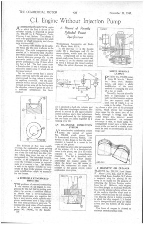
The novelty rests mainly hi the cylinder head, and this item is shown in the drawing. The main compression space consists of. a refractory-lined chamber (I) which connects with the cylinder via a doubly-divergent passage (2). At the narrowest point in this passage is a groove containing a ring (3) into which the fuel is led. The fuel comes from a float-chamber (4) and is metered by an adjustable needle-valve (5) which acts as the speed control.
On the suction stroke fuel is drawn past a one-way valve (6) and enters the space around the ring, where it remains by capillary attraction. On the . compression stroke, the air velocity through the neck carries some of the fuel up into the chamber, where it ignites as soon as a sufficient temperature has been reached.
The direction of flow then rapidly reverses, the combustion gases passing down through the passage, carrying the rest of the fuel with them into the cylinder, where they meet the rest of the compressed air. The time taken for combustion to be completed is stated to cause the wdrking pressure to approximate to a conitant _due. The scheme is said to be equilly suitable for twostroke or four-stroke engines, although some mlidifications might be necessary for the former. "
A REMOTELY CONTROLLED THROTTLE
'Pmproblem of remotely controlling the throttle of an engine is complicated by the fact that its setting must always be precise, a condition difficult to obtain with a servo-mechanism. Flexible diaphragms are sensitive but haVe a short stroke, whilst cylinder-andpiston mechanisms have a long stroke but their exact position is uncertain. To combine the good points of both systems is the object of a scheme shown in patent No. 590,482, by the Bendix
Westinghouse Automotive Air Brake Co., Elyria, Ohio, U.S.A.
. In the drawing: (I) is the throttle ' pedal (2) a diaphragm and (3) the servo-cylinder, which does the actual work. Compressed air is the motive power, and comes from a reservoir (4). A spring (5) on the throttle rod tends to move It towards the closed position.
When the driver depresses the pedal, air is admitted to both the cylinder and the right-hand diaphragm chamber. The piston is moved to the approximately correct position, and a final adjustment is then performed by the diaphragm; the two units are linked together by a rocking lever (6).
AN OIL-ENGINE COMBUSTION SYSTEM
AN ante-chamber combustion system forms the 'subject of patent No. 590,099, which comes from G. Lenormand, Garches, France. The novelty in this design is that the antechamber Ili located in a recess in the crown of the piston.
The drawing shows the bare essentials of the scheme; (1) is a hemispherical recess in the piston, and (2) a lid which converts it into a precombustion chamber. The lid is provided with . two holes, one of 'which closely approache.4 the injector nozzle (3), whilst the larger one _ .(4) "series to . admit the coinpressed Air from the cylinder to the piston crown: white combustion takes place. NOVEL BUS-SEAT LAYOUT
PATENT No. 590,030 comes from H. Morris, "Broadlea, ' Scott Park, Burnley, Lanes, and shows a slight modification of the usual method of arranging the seats of a bus or coach.
Normally, they are placed in pairs at " right-angles to the wall, but this inventor suggests that two separate seats be . used, one of which is at an angle to the other. The drawing shows a plan itiew of the proposed layout, which allows the occupants more space for the upper part of the body, although it brings heir feet rather closer; this, however, would cause no discomfort. An. Incidental advantage is that, in many cases, the arrangement would leave a little more room at the rear end of a vehicle, which could be used to accommodate an extra single seat
A MAGNETIC OIL CLEANER
PATENT No 590,173,. from Simms Motor Units,' Lid., and NV, Bryan, .both of Oak Lane, London, N.2, a magnetic plug for placing in the sump of an engine for the purpose of attracting. the ferrous foreign matter from the oil. Hitherto, such "magnets have been forged or machined from the bar, but the present scheme utilizes one of the modern high-flux alloys such as Alnico, which can only be cast to shape. The drawing shows a typical example in which the alloy magnet (I) is forced into ta hexagon-headed plug (2) which screws into the bottom of the engine sump.
This form of magnet is claimed to minimize manufacturing costs.