


Hydraulic Operation in A New Semi
Page 40
Page 41
If you've noticed an error in this article please click here to report it so we can fix it.
iutomatic Gearbox
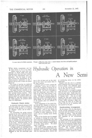
THE Hobbs transmission unit has been known to be in its experimental stages for some time, and, although its details might have been released earlier, they have been withheld until the final experimental work was completed. The last stages cyf evolution involved the development of the clutch-actuation mechanism to give a smooth take-up and to make the system foolproof.
Two forms of gearing are employed —a layshaft type for heavy vehicles and a planetary type, which would normally be used on lighter vehicles, such as cars.
The engine flywheel assembly of the layshaft pattern houses two hydraulically actuated friction clutches. These comprise the clutch friction plates (I), pressure plates (2), synthetic rubber diaphragms (3), and heat insulator plates (4) which separate the pressure plates from the diaphragms.
Hydraulic Clutch Action
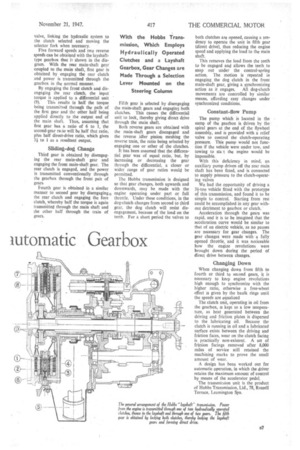
In operation, hydraulic pressure is fed from the pump (5), which is located in the base of the gearbox, to a number of " floating " valves, one of which is shown (6).
By overcoming the spring pressure exerted on the valve, hydraulic pressure lifts the valve and passes on to operate the clutch through the force exerted on the diaphragm. When the pump pressure is removed, the spring returns the valve and allows the oil to exhaust back to the pump Push-off springs, two of which are shown at (7), return the pressure plate to its non-driving position.
At higher speeds, tha centrifugal force on the floating valves should tend to open them to exhaust, but the system is designed so that the centrifugal pres
sure in the oil ducts acts on the outer end of the valves and retains them in the inner position.
A further series of valves, termed the " trafficating" valves, one of which is shown (8), is designed to exhaust the oil pressure from behind the diaphragm at idling speeds. The valve is arranged to keep the diaphragm space filled, but when in the inner open position it prevents build-up of pressure from the pump. Oil which is retained behind the diaphragm exerts a centrifugal action at idling speeds, but the push-off springs of the pressure plate are sufficient to overcome it.
Initial engagement of the clutch during take-up may depend on increase in centrifugal pressure if the gear has just been selected, or partial closing of the " trafficating " valve if the vehicle be moving away from standstill. Take-up is smooth in either application of the valves, and no hunting occurs during idling.
Either of the clutches may be engaged by opening or closing the pump pressure to the assol:ated floating valve, and one or both the clutches will engage or disengage with variation in engine speed at or near idling speeds. No clutch pedal is required.
The whole system, running in lubricating oil, retains the pressure-plate temperatures at a minimum, and, coupled with the insulating plates, ensures that no overheating occurs on the rubber diaphragms.
Integral with this unit is a gearbox which comprises three pairs of gears for forward speeds, with additional gears cut on the dog member and layshaft, and an idler gear for reverse.
The deg clutch is arranged to engage either the front or rear main-shaft gear with the main shaft. Baulk rings associated with the dog clutch have two sets of internal teeth. One set of teeth engages the dog teeth carried by the main-shaft gears with a certain amount of play, which, allowing a slight rotation, brings the other set of teeth out of line with the set of baulking teeth also carried by the gear.
Synchronizing Arrangement
By this means, when the dog clutch is moved towards engagement, it will be restrained until the speeds of the parts to engage are similar. Then the baulk ring will move under spring pressure into alignment in the coaventional manner.
The prototype of this transmission was fitted with mechanical linkage from the driver's cab to the gearbox selector fork, but the production models will be linked up to a hydraulic selector cylinder, which will be integral with the gearbox. This• cylinder, connected mechanically to the lever in the cab, will operate in a similar manner to a sleeve
valve, linking the hydraulic system to the clutch selected and moving the selector fork when necessary. •
Five forward speeds and two reverse speeds can be obtained with the layshafttype gearbox that iz shown in the diagram. With the rear main-shaft gear coupled to the main shaft, first gear is obtained by engaging the rear clutch and power is transmitted through the gearbox in the normal manner.
By engaging the front clutch and disengaging the rear clutch, the input torque is applied to a differential unit
(9). This results in half the torque being transmitted through the path of the first gear and 'the other half being applied directly to the output end of the main shaft. Thus, assuming that first gear has a ratio of 6 to 1, the second-gear ra.io will be half that ratio, plus half direct-drive ratio, which gives 3i to 1 as a resultant output_ Sliding-dog Change
Third gear is obtained by disengaging the rear main-shaft gear and engaging the front main-shaft gear, The rear clutch is engaged, and the power is transmitted conventionally through the gearbox through the front pail of gears Fourth gear is obtained in a similar manner to second gear by disengaging, the rear clutch and engaging the fore cluteh, whereby half the torque is again transmitted through the main shaft and the other half through the train of gears. Fifth gear is selected by disengaging the main-shaft gears and engaging both clutches. This causes the differential unit to lock, thereby giving direct drive through the main shaft.
Both reverse gears are obtained with the main shaft gears disengaged and the reverse idler pinion meshing the reverse train, the ratio being selected by engaging one or other of the clutches.
It has been assumed that the differential gear was of equal ratio, but, by increasing or decreasing the gear through the differential, a closer or wider range of gear ratios would be permitted_ The Hobbs transmission is designed so that gear changes, both upwards and downwards, may he made with the engine operating under part or full throttle. Under these conditions, in the dug-clutch changes from second to third gear, the dog clutch will resist disen&agement, because of the load on the teeth. For a short period the valves to both clutches are opened, causing a tendency to operate the unit in fifth gear (direct drive), thus reducing the engine speed and applying the load to the main shaft.
This removes the load from the teeth to be engaged and allows the teeth to snap out under the control-spring action. The motion is repeated in engaging, the dog clutch in the front main-shaft gear, giving a synchronizing action as it engages. All dog-clutch movements are controlled by similar means, affording easy changes under synchronized conditions.
Constant-flow Pump
The pump which is located in the sump of the gearbox is driven by the spiral gears at the end Of the flywheel assembly, and is provided with a relief valve to control the clutch-operating pressure. This pump would not function if the vehicle were under tow, and towing to stag the engine would be impossible.
With this deficiency in mind, an auxiliary pump driven off the rear main shaft has been fitted, and is connected to supply pressure to the clutch-operating valves
We had the opportunity of driving a 31-ton vehicle fitted with the prototype of this transmission, and found it to be simple to control. Starting from rest could be accomplished in any gear without detriment to gearbox or clutch.
Acceleration through the gears was rapid, and it is to be imagined that the acceleration curve would be similar to that of an electric vehicle, as no pauses are necessary for gear changes. The gear changes were made with a fully opened throttle, and it was noticeable how the engine revolutions were brought down during the period of direct drive between changes.
Changing Down
When changing down from fifth to fourth or third to second gears, it is necessary to keep engine revolutions high enough to synchronize with the higher ratio, otherwise a free-wheel effect is given by the baulk rings until the speeds are equalized The clutch unit, operating in oil from the gearbox, is kept to a low temperature, as heat generated between the driving and friction plates is dispersed to the lubricating oil. Because the clutch is running in oil and a lubricated surface exists between the driving and friction faces, wear on 'the clutch facing is practically non-existent. A set of friction facings removed after 8,000 miles of service stilt retained the machining marks to prove the small amount of wear.
A design has been worked out for automatic operation, in which the driver retains the maximum amount of control by means of the accelerator pedal.
The transmicsion unit is the product of Hobbs Transmission, Ltd., 78, Russell Terrace, Leamington Spa.