


Patents Completed.
Page 22
If you've noticed an error in this article please click here to report it so we can fix it.
Complete specifications of the following patents will be sent to any address in the United Kingdom by the Sale &ranch, Patent Office, Holborn, W.C., upon receipt of eightpence per copy.
A Parc clear Driving Wheel.
Aildays and Onions Pneumatic Engi. neering Co., Ltd., and C. E. Sims, No. 25,189, dated 13th November, 191L— This invention is applied to three-wheeled motor vehicles where a siingle driving wheel is used. This is generally mountea in bearings carried on laminated springs projecting from the rear end of the frame. On the back of the frame a cross shaft, baying arms at each end, is fixed, and these arms are connected by links or stay rods to the brackets in which the axle is mounted. By this construction the driv ing wheel is always kept normal to the road surface and torsion of the laminated springs is prevented. This invention is, of course, an attempt to eliminate the considerable friction and wear which takes place with certain vehicles of this
type
Quick-Acting Drill Sockets.
.T. W. Barnes, No. 22,498, dated 4th October, 1911.—According to this invention the shank of the drill, instead of being made with a Morse taper, is of meform diameter, and has two flats formed on it near the top. The end of the shank is rounded off. The socket for holding the drill is made slightly larger in ills meter than the drill shank, so that the drill may float to a certain extent in the socket; the top of the socket is domed to receive the top of the shank. Two slots are cut into the socket, and pads are fitted in them to slide transversely. When these pads are in their inner position they grip the flats on the drill; they are moved in and out by a sleeve, surrounding the drill socket and tapered at its lower end so that when it is depressed it forces the pads inwards. A spring lock is provided to hold the sleeve in its proper or lower position.
Metal Tire".
E. Schneider, No. 23,128, dated 19th October, 1911.—The tire described in this specification is one wherein metal treads are fixed in an ordinary metal rim. The
tire is formed bv a grating of hard metal in a series of I-shaped elements which are set side by side across the tread. These are curved upwards in order that they can be inserted into the rim IA the wheel. Soft metal blocks are then inserted in the gaps between them, and, when they are all in position, the curvature of the I-bars is removed by hammering them flat. The soft metal blocks are hammered down to fill up the spaces, and they are then left slightly projecting beyond the plates. This is an attempt to provide a metaltreaded tire in which the tread can be renewed when worn, and without the use of rivets, which are apt to be sheered off when assembling. the tire.
For Hot Bearings.
R. C. J. Boaler, No. 22,839, dated 17th October, 1911.—A casing of steel or other metal having a small co-efficient of expansion is screwed into a bearing, and inside it there is fixed a rod of zinc or other metal having a larger co-efficient of expansion. A contact screw in an insulated disc in the top of the casing is set close to the top of the zinc rod. Overheating of the bearing causes expansion of the zinc rod and this makes contact with the screw, and completes an electric circuit to operate some suitable form of alarm. This may take the form of a bell or lamp situated in the engine-room or some other convenient place.
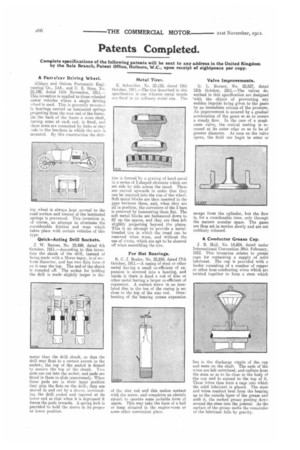
Valve Improvements.
U. L. Burner; No. 22,527, dated 12th October, 1911.—The valves described in this specification are designed 'with the object of preventing any sudden impulse being given to the gases by an immediate release of the pressure. An improvement is secured by a gradual acceleration of the gases so as to ensure a steady flow. In the case of a mushloom valve, the conical seating is recessed at its outer edge so as to be of greater diameter. As soon as the valve opens, the fluid can begin to enter or
escape from the cylinder, but the flow is, for a considerable time, only through the narrow annular space. The gases are thus set in motion slowly and are not suddenly released.
A Conductor Grease Cup.
J. B. Halt, No. 14,834, dated under International Convention 24th February, 1912. This invention relates to grease cups for containing a supply of solid lubricant. The cup is provided with a feeder consisting of a number of copper or other heat-conducting wires which are twisted together to form a stem which
lies in the discharge nipple of the cup and rests on the shaft. The ends of the wires are left untwisted, and radiate from the stem so as to lie close to the body of the cup and to extend to the top of it. These wires thus form a cage into which the solid lubricant is placed. The stem and wires conduct heat from the bearing up to the outside layer of the grease and melt it, the melted grease passing down around the stem into the journal. As the surface of the grease melts the remainder of the lubricant falls by gravity.