


A Résumé of Recently Published Patent Specifications
Page 48
If you've noticed an error in this article please click here to report it so we can fix it.
A Resilient Body-to-Chassis Connector
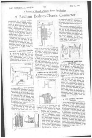
I NTENDED for positioning, between body' and chassis, a resilient member, shown in patent No. 597,239, comes from the Brush Electrical Co., Ltd., and F. Rayer, both of Nottingham Road, Loughborough. The unit consists of a rectangular box (i) which is attached to the chassis, containing a wedge (2) fixed to the body. The intervening space is filled with rubber (3) and the whole assembly is bonded into a one-piecestructure.
Under load, the rubber is placed in both compression and shear, so that resistance to movement increases substantially with an increase in load. To act as end stops, the rubber is extended at points 4 and 5, so that at the limit of movement a ' buffer action is obtained.
NOVELTY IN IGNITION SYSTEMS
A NEW type a ignition system is 1-"I shown in patent No, 597,348. which 'comes from W. Luttmer, and Winne Development, Ltd., 1, Queen Victoria Street, London, E.C.4. The chief novelty is the method of working
the make-and-break; this is electrically operated by the pulsations of an alternator driven by the 'engine crankshaft.
Referring to the drawing, 1 and 2 are two windings of an engine-driven a.c. generater, the frequency of which is proportional to the engine speed. The smaller of the two windings supplies a coil (3), which is thereby caused to oscillate in a magnetic field. ' The action of this unit resembles that of a moving-coil loudspeaker.
The main part of the generator winding is •connected in series with the high-tension coil (4), and the latter works in the usual way when the points (5) are closed and opened by the oscillating coil. As the vibration Of the latter is Synchronized with the engine speed, it gives precise timing; an advance-retard mechanism is, however, incorporated.
The points (6) on the other side can be wired to an accumulator for charging purposes; although the supply is a.c., the oscillating coil "sorts out" the half-waves, and directs tht_ positive to. one. side and the negative to the other—in other words, _ it is a synchronous rectifier. The specification illustrates also the actual construction of the coil-operated make-and-break.
A SPRING MADE OF RUBBER
ARUBBER unit, intended to replace the conventional steel ,spring of a suspension system, is shown in patent
No. 596,333, by the Firestone Tire and Rubber Co., Akron, Ohio, U.S.A. The unit also has the property of offering greater resistance to cornpression than to extension.
The drawings show the spring and a suspension system embodying it.' The unit consists of a central guide-tube, around which is arranged a number of saucer-shaped -rubber discs (1) faced on one side with sheet metal. Each rubber member is provided with a shallow groove on one face, which connects with a hole (2). All the holes
are lined up in assembly and communicate with an outlet (3). Air-cooling is the object; in action the unit acts as a pump, discharging hot air and inspiring cold.
The increased resistance to compression is Created by the shape of the inner lips (4) of the discs .'• These bulge inwardly during compression and grip the central thernber, but on the return stroke their sloping, face's lead and do not obstruct the motion' s° much. This effect is increased by 'using a
thixotropic ' lubricant, that is a substance whieli is sOlid when free but which liquefies under stress: A CONVERTIBLE WHEEL FOR TRACTORS
PATENT No. 597,153 comes from H. Merritt, A. Smith and David Brown Tractors, Ltd., Melthann
Huddersfield, and shows an improvement in thedesignof -tractor wheels. The .aim is to provide an easily attached rim which can be quickly changed to suit the particular job in hand.
The drawings show three different typesof rim and the method of attachment. The wheel proper has spokes' (1) terminating in hollow bosses (2) to which can be bolted the various types of rim.' ,The drawing on the left shows a widely speed pair of bands., the centre drawing the same pair turned about so as to give a narrow tread, whilst the right-hand one illustrates a pair of, rings adapted for running on a ridge. These, too, can be reversed if a V-shaped tread be requited.
A NEW. SECTION FOR BODY PILLARS FROM the Brush Electrical Engineering Co.. Ltd., and F. Rayer, ,both of Nottingham Road, Loughborough, conies, in patent No. 596,984, a method of constructing body pillars and similar components.. The basic unit is, a pair of rolled or extruded sections which can be united to form a pillar assembly.
The drawings show the pair of sections, which are similar except for the position of the central web.. The lower drawing is of a sectioned assembly in which the channels are filled-in with wood. Wood screws are used to attach the interior facing, in this case a window frame, and the exterior panelling. -Other woodscrews, at right angles, unite the half-sections.