


B.M.M.O. Introduces 8-ft. Single-deckers
Page 27
If you've noticed an error in this article please click here to report it so we can fix it.
THE prototype S model
decker under-floor-engined bus single
THE prototype S model
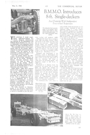
decker under-floor-engined bus chassis, designed, manufactured and operated by the Birmingham and Midland Motor Omnibus Co., Ltd., has an independent front-suspension system added to its many unorthodox features.
This suspension system, in the experimental stage for the present, offers a reduction in weight and increased riding comfort. From the success of this experiment it appears likely that it will be introduced in future models.
Twin coil springs support the independent wheel-carrying assemblies on each side of the frame. WoodbeadMonroe telescopic hydraulic shock absorbers are used to damp out periodicity of the springs. Rubber bushes, of Harrisflex manufacture, are used at all the bearing points to reduce lubrication and ensure silence.
Singledecker under floor engined chassis of 8-ft. width are now in operation on the "Midland Red" services. The additional 6 ins, affords an extra 2 ins, in the gangway width, as well as increasing the width of the seats to 36 ins. Like its predecessors, the S8, as it is designated, has a seating capacity for 40 passengers. A forward entrance is provided, the door to the passenger compartment opening out from the central gangway and swinging towards the driver's cab.
The body, mounted on Silentbloc bushes, is of all-metal construction. The saloon side frames have been made as narrow as possible to give the maxi mum sealing and gangway width. Although the frame line is comparatively high (providing shallow wheelarch boxes in the body), the 58 passed
the tilt test with ease. Tilted on the off-side wheels, the complete vehicle. loaded to regulation weight. maintained its balance with the tilt table set at an angle of 41 degrees. The chassis weighs 4 tons 5 cwt. and the complete vehicle 6 tons 8 cwt. Wheelbase is 16 ft.
Designed and constructed at t he company's works at Birmingham, the six-cylindered direct-injection oil engine, with a bore of 4.45 ins, and stroke of' 5.25 ins., develops 105 b.h.p. at 1,700 r.p.m. (its governed speed). The maximum torque is 343 lb/ft. ri 1,200 r.p.m.
Positioned at 5 degrees from the horizontal, the power unit is carried below the chassis side member by three-point rubber suspension. The rear suspension is in the form of an anntlith around part of the clutch housing, retained in position by two semicircular casings. The front mountings consist of large-diameter rubber-tometal bonded bushes positioned to isolate low-frequency oscillations.
An aluminium-alloy valve cover to each cylinder head incorporates an airintake passage. Included in this airinduction system is a large Talflow filter, specially designed for this engine. Provision is made for easy removal of the element for cleaning and replenishing the oil supply. Air supplied to this filter is drawn through ducts connected to on inlet in the driver's cab, The fuel-injection pump is mounted at right angles to the crankshaft and is
driven from it by bevel gears. Twinbelt drive from a crankshaft pulley is provided lot the water pump and dynamo. Made in two pieces, the ily
wheel starter ring can be removed without disturbing other components.
The gearbox is mounted independently in the frame and retained in position by four rubber-bonded insula
tors. Fourth, third and second gears are of constant-mesh pattern, whilst bottom and reverse are plain sliding gears. A shaft employing Layrub couplings carries the transmission between the engine and gearbox, and the propeller shaft is fitted with Whittaker universal joints equipped with needle-roller couplings.
A fully floating overslung-worm rear axle is used. As the engine and gearbox transmission line are offset, the worm-pot is similarly offset to the off side to maintain a straight line. The four-wheel brakes are hydraulically operated. aided by a Lockheed continuous-flow master servo cylinder unit. A 3-to-I boost pressure is provided from the unit.