


Progressive Methods at Luton.
Page 2
Page 3
Page 4
If you've noticed an error in this article please click here to report it so we can fix it.
A Brief Description of Some of the Ingenious Methods of Manufacture in Vogue at the Works of Commercial Cars, Limited.
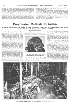
In "THE COMMERCIAL MOTOR" Of the 20th September, 1906, we gave a short description of the new works at Biscot Road, Luton, of Commercial Cars, Limited: the total ground area of the land owned by this company at Luton is about 3i acres, and, at the date (looted, the buildings themselves covered a matter of one acre. Since that time, considerable progress has been made, and we can record without fear of contradiction that there is no motor manufacturing concern in this country which has brought its name so prominently before the public in so short a time. On the occasion of our earlier visit, there was practically a single building, one end of which was devoted to the offices, and the remaining portion to the machine, erecting, fitting and stores departments, and the space covered by these four departments was about 34 feet by 16o feet. The original structure has now been supplemented by others, which have been erected from time to time, as has been found neces
sary, and the newer ones comprise a coppersmiths' shop, test house, casehardening morn, smiths' shop, repair shop, body shop, and paint shed. The whole of the main buildings are heated by means of slow-combustion stoves, the Uptakes of which lead into horizontal sheet-metal flues; these flues are suspended from the roof girders, and they converge into one main uptake. The hot-water apparatus, by means of which the whole of the offices are heated, is built into the base of this shaft.
When we recently called at the works, we had the pleasure of being received by the Chairman of the directors, Mr. H. C. B. Undcrdown, and the general manager, at Luton, Mr. F. H. Mitchell. Mr. C. M. Linley, the works manager, was kind enough to show us the most recent improvements which had been effected with a view to the rapid production of parts which must be absolutely interchangeable. The first department to be visited was the drawing office, where the system in vogue was carefully explained; the" operation cards," which are here prepared for each detail part, arc well worth the consideration of many works where no such system exists. On these cards is enumerated the order in which the various operations are to be.made, and also the tools, jigs, fixtures, or gauges that are required for their accurate production. It is beyond the authority of all but one person in the works to allow of any departure from the order of procedure laid down on these cards. The personal element is thereby almost entirely eliminated, and, as the scheme extends throughout every department, and includes such operations as the setting of valves, timing of magnetos, and other important operations which in many shops are left to the judgment of one " smart " man, it is especially commendable where the latter has become a source of objection.
Passing from the drawing office to the machine shop, one of the first tools which attracted our attention was a special lathe for automatically turning round bars to any given diameter. The adjustments on this lathe were extremely simple, and consisted of a cross feed, with a large circular index, which indicates the diameter. of the bar at any time during the process of turning. To ensure that the tool is always set in exactly the same position, it is ground, in a special fixture, to a constant angle, and, before clamping the tool on to the saddle, this angle portion is caused to butt up against a stop on the saddle.
Near to this indicating lathe, which, by the way, is only used for roughing out gearbox shafts and other parts which are finished on a large Norton grinder, we came across a very ingenious fixture for holding connecting rods while the two ends are being bored. We illustrate this device, and it will be seen that the " fixture " is mounted on, and is eccentric to, the face plate of the lathe. Working within the fixture is a small face plate, on which the connecting rod is clamped. This face plate is provided with two definite notches, exactly iSo degrees apart, and in either of these notches a springloaded plunger, which is mounted on the base of the fixture, is allowed to engage. When the face plate is secured in either of its two working positions, it is clamped, and prevented from turning, while work is in progress. After one end of the connecting rod has been bored and faced, the clamping screws can be the face plate swung round through i8o degrees, and again secured by the clamping screws, the other end of the connecting rod being immediately bored and faced in a similar manner. This arrangement isa very neat one, and its use not only ensures that the two bores of the connecting rod should beat .precise distances apart,,btiOt also obviates any chance of their not being parallel to each other.
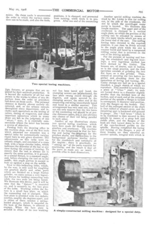
Another of our illustrations shows two special boting machines, which have been made for dealing with the gearbox and crankcase. The machine seen in the foreground is that for boring and facing the,hou.sings. for the gearbox shafts, and themachine in the background performs similar duties for the crankshaft and camshafts of the engine there is practically no " setting up" of the parts required for machining, and the result is that all the parts so made are as nearly, as possible alike in their dimensions. Another special milling machine devised by Mr. Linley is that for milling out, in the side of the crankcase, the slot by which the centrifugal water pump is located. We illustrate this simple machine. The upper part of the crankcase is clamped to a vertical angle plate, on which the position of the casting can be adjusted by means of the two taper blocks which are seen at the lower end of the case. The casting having been elevated to the required position, it can then be firmly secured to the angle plate while the slot is counter bored and faced by a compound milling cutter that is mounted on the ene of' the driving spindle.
For the purpose of turning and boring the crankshaft and big-end bearings, a very ingenious method has been devised by Mr. Linley. The brasses are, of course, cast in halves, as is the usual practice, and the first operation consists of grinding the two. flat faces on a disc grinder. Then, instead of sweating the two halves together and chucking them for the operations of boring and turning, Mr. Linley clamps one half on to a special mandrel, a rough sketch of which we reproduce. This mandrel is turned from a piece of " Ubas " steel ; its ends are turned down to a diameter slightly smaller than the finished bore of the bushes, and at each end of the enlarged. portion of the spindle a flange is turned to correspond, in diameter and position,. with the flanges on the bushes. One half of the enlarged section of the shaft is then milled or shaped away, and the remaining part is hardened and ground. to gauge. The " half brass " which is to be machined is then secured to this. spindle by means of a strap bolt and saddle plate, and the flanges of the bush are then turned down to the size of the case-hardened guides on the spindle. Having completed the facing and turning of the flanges, a pair of these brasses are then mounted on another spindle, integral with which is
fa conical, cupped flange, and, between this flange and a similar loose flange, the bush is secured by a large clamping
screw.; while on this mandrel, the straight plain part of the bush is
• turned. The external portions of the bush having thus been completed, the two halves are then chucked, in a special fixture, and they are bored and .given a ragged internal surface to receive the white metal lining. Any two may be used together.
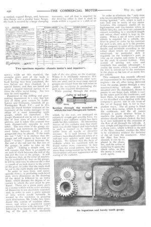
Prominent in the milling and gear-cutting department is a very fine battery of three gear cutters by Ludw. .Loewe and Company, Limited, of 30, Farringdon Road, E.C., and in this • room we found further evidence of the ingenuity of the works manager in the -shape of a most interesting tooth gauge, which we reproduce. The gauge illustrated can be set to suit any one of four sizes of gear wheels or pinions, and it takes into account two teeth diametrically opposite to each • other. The two arms of the gauge are extended, and terminate in case-hardened faces, between which a steel gauge-rod may be placed. If the teeth .are cut " full," it is obvious that the gauge rod will require to have one or Anore " feelers " inserted between the flat end of the rod and the flat face of the gauge, in order to take up the ." slack." Taking a simple case, we will assume that there is 4-1,000ths of . an inch of slack between the end of the rod and the face of the gauge. It will be obvious that, as the error of machining is multiplied by four on the gauge, 'it will be necesarv to advance the cutter r-t,000th of an inch nearer to the centre . of the gear, in order that the teeth shall be cut to the right depth and thickness.
In order to save time, and consequently money, in producing each detail part, every dimension on the drawing of the detail is followed by an index letter, which denotes the degree of ac, curacy to which the part must be produced. There are a great many parts on a motor vehicle where strict accuracy of dimension is not absolutely essential, and, in order to save a great amount of time which would normally be wasted by the workmen in gauging such dimensions, Mr. Tinley has introduced this system of machine allowances, and when a machinist comes across a dimension with the letter " E " following it he knows that strict gauging of the part is not absolutely
necessary, and all that is required by the drawing office is that it shall be made •within a I-32nd or a t-t6th of an inch of the size given on the thawing. Where it is absolutely necessary that strict accuracy be enforced, other symbols are used, and in most cases special gauges are issued from the tool room to guide the machinist in producing the part to the required dimensions.
While passing through the stores, which, by the way, are managed on extremely simple and sensible lines, we noticed a new radiator which has been made for this company. An interesting feature of this radiator was that every seam was double lapped and interlocked in such a manner as to relieve the solder from all tensile or shearinkr, stresses. It is well known that the ordinary lapocd-and-soldered joints of a radiator very quickly split and cause leakage. We believe that the form of radiator which WC examined will be found rather more expensive, in first cost than the usual pattern, but this is more than compensated for by the stout construction and neat appearance of the casing of the radiator. In order to eliminate the "only man who knows anything about wiring, and timing ignition " evil, which is such a very real one in many of our motor factories, this company stocks all its high-tension and low-tension Wires in definite lengths, and these are painted in colours according to a standard length and colour chart which is kept in the stores. When a set of wires and terminals is _required for a vehicle, the fitter is given an order by his foreman for such a set, and, as it is the practice of this company to paint all its electrical details and terminals according to the colour chart which we have already mentioned, no particular skill is required, on the workman's part, to wire up an engine and make it ready for the road, in correct fashion. This system of serving out wire and terminals has another advantage : it avoids the waste which is usual when the wire is served out to the workman in the shops at the 'rate of so many feet per vehicle.
This company has recently effected an improvement in the lubrication of its engines : the oil, after being delivered from the pump, passes through a very massive-looking tell-tale, which is mounted over the dashboard; thence it passes to one large duct, which is cast in the upper part of the crankcase; and from there, in much the same manner as we described when dealing with this company's 3o-cwt. van in our issue of the 1st of August last, is led to four shallow trays. The oil pump is fitted in a very deep sump, which is seen in the crankcase, and the oil passes through a gauze strainer before it reaches the pump • chamber : if this strainer should become choked, the fact is at once indicated by the cessation of the flow of oil through the tell-tale. A very simple and ingenious application of a check valve, which is fitted in the end of the filter chamber, enables the filter to be withdrawn without the draining of the oil from the crankcase. After the filter has been cleaned, it can be replaced in the chamber, and the action of replacing it opens the check valve, so that the pump is ready to work again.