


AIR SPRINGS NOT FAR AWAY
Page 46
Page 47
Page 48
If you've noticed an error in this article please click here to report it so we can fix it.
Dunlop Advances with Air Suspension' Include Adaptations of Existing Chassis to Incorporate Pneuride Air Bellows : Little Extra Weight .• Improved Unladen Ride
By John F. Moon, A.M.I.R.T.E., A.S.A.E.
IN view of the progress that has been made with air suspension in the United States, Germany, Holland and Italy, it obviously cannot be much longer before such suspension systems are available as production options on British commercial vehicles. Announcements of such developments have so far been few, and those that have been made have referred only to buses and trailers.
At the beginning of this month, however, the suspension department of the Dunlop Rubber Co., Ltd, Foleshill, Coventry, announced that they had converted a Commer 7-ton oil-engined vehicle to incorporate their own Pneuride air suspension units. At the same time the Dunlop Rim and Wheel Co., Ltd., fitted disc brakes to the vehicle. Thus, although only in experimental form, this Commer is one of the most highly developed goods vehicles in Great Britain. Commer Cars, Ltd., have co-operated in this development.
One Year's Progress
It is little more than a year since Dunlop Pneuride air springs were first fitted to a road vehicle—an A.E.C. Reliance lightweight underfloor-engined passenger chassis. The suspension department is rapidly growing in size, however, and various schemes are under way for the conversion of existing and projected goods and passenger chassis, and private cars.
The Commer conversion shows the progress that has so far been made in this field. It was briefly described and illustrated in last week's issue of The Comntereial Motor. It consists of independent front suspension, with a single bellows unit at each wheel, whilst at the rear a balance-beam system is employed, with two air springs at each side.
The additional weight caused by the conversion is said to be less than 100 lb. It is expected that when it is possible to c 10 incorporate air suspension in a vehicle at the drawing-board stage, there will be a definite saving in the overall weight when compared with conventional leafspring systems.
To make the front-suspension conversion the original Commer axle beam was split, the centre section removed, and the two outer sections pivoted to a special frame cross-member by rubber bushes carried in brackets bolted to the axlebeam sections.
By this means lateral location of the front wheels was assured, but to provide longitudinal location and to absorb braking torque, longitudinal radius arms have been employed. These are bolted to the original axle spring pads at their forward ends and pivoted to the chassis frame by spherical rubber bushes at the rear ends. The radius arms have been fabricated from channel-section members, secured hack to back throughout most of their length, hut forked at each end to facilitate anchorage.
At the forward end of each radius arm a robust bracket is bolted. each also being secured directly to the axle arms close to the king-pins. The brackets carry the lower rings of the air-spring bellows. The "upper ends of the bellows bear against large brackets bolted to the chassis frame.
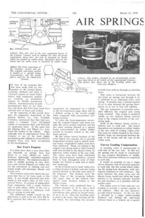
The bellows units employed have a nominal diameter of 10 in. and a load capacity of 2 tons. They are of the twoconvolution type, giving an overall stroke of up to 6+ in. Only one levelling valve is used at the front, this working off the left wheel, but controlling the pressure in both front bellows through an isolating valve.
This valve is interposed between the two front air springs and through it air is admitted to or exhausted from, each spring. It permits only a limited amount of air to pass between the springs themselves, so as not• to lose roll stability.
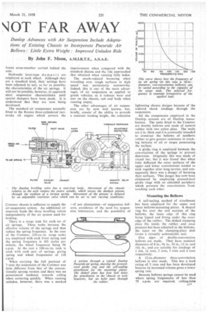
The rear suspension is naturally somewhat different, the original axle casing being retained. This casing is mounted solidly on two balance beams, secured close to the original position of the rearspring pads.
Each of the balance beams carries a bellows unit at each end. The beams themselves are mounted on rubber bushes at the rear ends of trailing radius arms The arms are rubber-bushed to the frame. Rubber stops are interposed between the ends of the beams and the tops of the radius arms.
Uneven Loading Compensation
A levelling valve is incorporated at each side of the rear axle. In this way the springs can be made to compensate for any unequal distribution of weight. Two 10-in.-diameter bellows are employed at each side.
It would be possible to use a single 141-in.-diameter unit (4-ton load capacity) at each side, but this would entail reducing the spring-base dimension, with subsequent reduction in roll resistance. The space between the inner tyres and the chassis frame would not allow the larger bellows to be located centrally beneath the side members, as is possible with the smaller units.
The radius arms at front and rear are stressed to provide a certain amount of roll stiffness. They do not, however, provide lateral location. At the rear this is afforded by a single rubber-bushed Panhard rod, linking the right-hand balance beam to a bracket on a special frame cross-member carried behind the axle.
Hydraulic lever-type dampers are , employed at each wheel. Although they are a standard kind, their settings have been adjusted to suit, as far as possible, the characteristics of the air springs. It will not be possible, however, to approach ideal suspension characteristics .until special dampers have been made. It is understood that they are now being developed.
The standard air compressor normally fitted to the Rootes three-cytindered twostroke oil engine . which powers the Commer chassis is sufficient to supply the air-suspension system. An additional air reservoir feeds the three levelling valves independently of the air system used for braking.
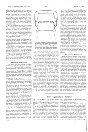
There is a surge tank for each -set of air springs. These tanks increase the effective volume of the springs and thus reduce the spring frequency. In the case of the Commer, 220-cu.-in. surge tanks are employed with each front spring and the spring frequency is 103 cycles per minute, the wheel frequency being 94 c.p.m. At the rear a 100-cu.-in. tank is used with each pair of springs, giving spring and wheel frequencies of 118 c.p.m, When carrying the full payload of 7 tons the suspension of the Commer was little different from that of the conventionally sprung version and there was no pronounced tendency towards rolling when cornering quickly. When running unladen, however, there was a marked improvement when compared with the standard chassis and the ride approached that obtained when running fully laden, The much-reduced bouncing when travelling over rough surfaces at high speed was ' particularly noteworthy. . Indeed, this is one of the main advantages of air suspension as applied to goods vehicles, as it reduces wear and tear on the chassis, cab and body when running empty.
The other advantages of air suspension are by now well known, but, briefly, consist of the ability to provide a constant loading height, the reduction —if not elimination--of suspension failures, avoidance of the need for suspension lubrication, and the possibility of lightening chassis designs because of the reduced shock loadings through the suspension.
. All the components employed in the Dunlop systems are of Dunlop manufacture. The units fitted to the Commer are double bellows and made of natural rubber with two nylon plies. The walls are *in. thick and it is eventually intended to construct the bellows of synthetic rubber to give greater resistance to cracking beeause of oil or ozone penetrating the surface.
A girdle ring is employed between the convolutiOns of the springs to prevent distortion. Originally this was made of round bar, but it was found that when fully deflected the outer surfaces of the upper and lower convolutions tended to stick together after long service, and consequently there was a danger of harming their surfaces. This danger has now been eliminated by employing pressed-steel .girdle rings with an extended periphery which prevents the convolutions from touching each other.
Mounting the Bellows
A self-sealing method of attachment has been employed for the upper and lower bellows-mounting plates. A shaped ring fits over the end sections of the bellows, the inner edge of this ring being lipped and fitting under the 'outer edge of the rubber. The dished clamping plate fits inside ihe rubber and once pressure has been admitted to the bellows, the taper on the clamping-plate dish forms a virtually unbreakable seal.
Five • sizes of double-convolution bellows are made.They have nominal diameters of 8 in., 94in., 10 in„ 12-in. and 144in., and are suitable for loadings of 1 ton, 14torts, 2 tons, 3 tons and 4 tons respectively.
A 12-in.-diameter three-convolution bellows is also made. This has a load rating of 3 tons and has been developed because its increased volume gives a lower spring rate.
Because bellows springs cannot be used where spring frequencies of less. than 75 e.o.m. are required, rolling-lobe el ,
diaphragm springs nave been developed. These have load capacities of 11 tons, 2 tons and 3 tons, and are capable of giving frequencies as low as 40 c.p.m.
The rolling-lobe spring is designed with an integral surge tank and is more compact than the bellows type. This. combined with the lower frequencies available, makes the diaphragm pattern more suitable for cars and light commercial vehicles.
All the Dunlop springs are designed for a maximum normal working pressure of 80 p.s.i., but they will operate satisfactorily at 100 p.s.i. and are tested to a bursting pressure of 650 p.s.i. Bellows units will work satisfactorily at pressures as low as 4 p.s.i., but diaphragm units must he operated at not less than 30 p.s.i. for reasonable results.
So far as frequency ranges are concerned, bellows units are designed for frequencies of between 80 and 125 c.p.m., whilst the lobe " type theoretically can provide characteristics of between 10 and 100 c.p.m, The Dunlop levelling valves employed incorporate an adjustable hydraulic damping device to give the required delay period in the system, This is to ensure that minor road fluctuations do not cause changes in the bellows pressures.
Cast iron is employed for the bodies of the valves, whilst the dash-pot delay pistons are of aluminium. A silicone fluid is employed for lubrication and delay purposes.
Adjustable Delay Valve
The delay can be varied according to service needs, but 8 sec. is found to produce the optimum results with commercial vehicles. The valves are virtually insensitive to large changes in ambient temperatures, as a slight bleed is allowed round the damping pistons and at low temperatures it is greatest, thus allowing the less viscous oil to pass round the pistons at the same rate as when the temperature is very high.
It is not thought necessary to incorporate safety devices in an air suspension system, because, even should an air pipe or bellows fracture, the chassis would be supported on the axle by the bump rubbers and the axle would be located by the radius and Panhard rods. Thus the vehicle could still be driven, whereas with conventional leaf springs this would not always be possible in the event of a main-leaf breaking.
The estimated life of the bellows is far greater than that of any vehicle to which they are likely to be fitted, whilst that of the levelling valves is anything up to 500,000 miles. The main thing likely to restrict the life of these valves is the admission of improperly filtered air to the system, although each valve does carry filters at the inlet and exhaust ports.
So far as adaptation to existing vehicles is concerned, any vehicle with an air compressor can be modified, the quantity of air required not being large. A normal 3-4-cu.-ft. compressor is more than sufficient and if compressors with an output as low as 1 Cu. ft. were available, they could be used satisfactorily.
c 1 2
It would be possible, with air suspension, to vary the ratio of frontto rearwheel air braking according to the load. This would greatly increase tyre life, because it would reduce the tendency for the rear wheels to lock when unladen.
Even with conventional braking systems tyre wear is found to improve with an air suspension system, because of the more constant contact with the ground.
At the moment it is likely that vehicles with air suspension will be slightly more expensive than others. When manufacturers start to use it widely, prices will probably be equal. At the moment the levelling valves are the most expensive single items.
All the Dunlop air-suspension systems so far developed have been of the opencircuit type, in which air is exhausted through the bellows to the atmosphere. This arrangement is much more simple than the closed-cycle system, in which air from the bellows is led back to the compressor for restorage. The main disadvantage is the noise of exhausting air when the load is removed, but this is unimportant with a commercial vehicle.
The disc brakes also fitted experirnen tally to the Commer are standard Dunlop units. The discs themselves, which are of chromidium iron, are attached to carriers and bolted to the wheel studs, being offset inwards to allow room for the calliper units. Solid discs are used, as their area is large enough to give adequate heat dissipation without the need for ventilating slots. They are 154 in. in overall diameter and 11 in. thick.
Double calliper units are employed at front and rear wheels, each containing four sets of rectangular friction pads. The calliper units are fitted behind the wheel centre lines, and are attached to the axles by a two-bolt fixing on to special brackets.
Much weight is saved by using disc brakes compared with the original drums. The exact figures for the Commer conversion are not known, but in the case of high-powered private cars a disc-brake assembly weighs 19 lb., whilst the drum brake weighs 34 lb. complete.
Air-hydraulic actuation has been employed for the Commer disc brakes, a dual circuit being used for safety. A separate disc on the rear-axle input shaft is operated by the hand lever and the callipers are actuated through a normal rod linkage
Air-pressure Actuation?
Although all disc brakes so far manufactured, other than the mechanically operated hand brakes, have had hydraulic actuation, a disc brake might be designed to work off a straight air-pressure system.
Presumably, some form of linkage, as employed with a hand brake, would be incorporated to allow the use of standard types of piston or diaphragm actuators. This would greatly enhance the suitability of disc brakes for heavy commercial vehicles, as it would reduce the number of non-standard components.
When driving the COMMer normally, there was no appreciable difference in braking compared with that obtained with drums. It is not intended, in fact, that the disc brakes should give greater retardation rates. .Their prime purpose is to reduce fade to a point where it virtually becomes non-existent, eliminate the need for frequent brake adjustments, increase the life of the frictional material, and make the replacement of the friction pads a matter of minutes, instead of hours.