


Patents Completed.
Page 30
If you've noticed an error in this article please click here to report it so we can fix it.
TREMBLER DEVICE. — Prested. — 22,606, dated 12th October, 1906.—The spring (e) is fixed to one terminal member (c) and makes contact with a second terminal member (d). The armature If) is pivoted at one end by ear-pieces thereon which engage slots in a block (gh and it is maintained in the raised position at that end by a spring (i). The end remote from the pivot is forked, and the free end of the spring (el lies between the two parts of the fork. A lever (k) is carried by the block (g) and, when this is in the position shown in Fig. 1, the armature is free to operate. When it is moved into the position shown in Fig. 2, the armature is depressed and held down against the magnetic iron core (6) of the induction coil. The Object of thus holding the armature
down is to enable the user to cut out any one coil of a series of coils in a multicylinder engine for the purpose of locating any inefficiency in sparking.
VALVE MECHANISM.—Martin and Another.—No. 16,193, dated 2nd February, 1906.—The object of this invention is to maintain the operating parts of the valve always in contact with each other, so that shock is avoided, and the sparking device is operated by the same mechanism. The opening of the valve (e) is effected by a rocking lever (h) which carries a cylinder (j) wherein works a plunger (i) carried on one end of the operating rod (g). In the head of the cylinder a small orifice (k) is provided so that the plunger and cylinder together act as a dashpot, and a spring (1) operates between this cylinder and a collar on the rod (g). The rod (g) is reciprocated by a cam (a) having a raised portion (b) and a recessed part (d). When the raised part (b) passes beneath the rod, the valve (c) is opened by the plunger (i) coming into contact with the bottom of the cylinder, but when the rod (g) drops into the recess (d), the cylinder (j) does not follow it and, consequently, the parts (k, 6-) are maintained in contact. The spring (1) operates to keep these parts in contact. Pivoted to the rod (g) is a lever (n) which co-operates with an arm (p) whose end (f) makes contact with a stop (e) in the cylinder. The end (q) of the arm (p) is so shaped that when the rod (g) rises over the projection (b) of the cam, the end of the rod (n) slides over the part (q) without moving the arm. When, however, the rod drops into the recess (d) the end (f) of the arm comes into contact with the corresponding part (e) so that, as the rod again rises out of the recess, the parts are separated and the spark occurs. The arm (n) is pivoted at one end to an arm (t) and, by raising or lowering this arm, the time of the spark may be varied.
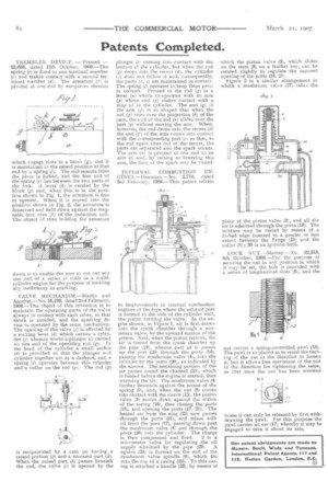
INTERNAL COMBUSTION ENGINES.—Heasman.—No. 2,710, dated 3rd February, 1906.—This patent relates
to improvements in internal combustion engines of the type where the exhaust port is formed in the side of the cylinder wall, the piston forming the valve. In the engine shown, in Figure 1, air is first drawn into the crank chamber through a nonreturn valve, by the upward motion of the piston. Next, when the piston returns, the air is forced from the crank chamber up the pipe (19), whence part of it passes up the port (20) through the ports (18), passing the mushroom valve (4), into the cylinder by the ports (26), as indicated by the arrows. The remaining portion of the air passes round the channel (25), which is heated before the engine is started, thus warming the air. The mushroom valve (4) further descends against the action of the spring (5), and, When the nut (8) comes into contact with the sleeve (15), the piston valve (3) moves down against the action of the spring (16), thus closing the ports (18), and opening the ports (17, 21). The heated air from the ring (25) now passes through the ports (21), and mixes with oil from the port (17), passing down past the mushroom valve (4) and through the ports (26) into the cylinder. The charge
is then compressed and fired_ 2 is a micrometer valve for regulating the oil supply admitted by the pipe (29). A square (24) is formed on the end of the mushroom valve spindle (9), which fits into the top of a. casing (22). To this casing is attached a handle (23), by means of
which the piston valve (3), which slides on the stem (9) on a feather key, can be rotated slightly to regulate the exposed opening of the ports (18, 21).
Figure 2 is a similar arrangement in which a mushroom valve (27) takes the place of the piston valve (3), and all the air is admitted through the ports (18). The mixture may be varied by means of a forked edge inserted to a greater or less extent between the flange (Si) and the collar (8); 30 is an ignition bulb.
LOCK NUT.—Murray.--No. 22,213, 8th October, I906.—For the purpose of securing the nut in any position in which it may be set, the bolt is provided with a series of longitudinal slots (6), and the nut carries a spring-controlled pawl (13). The pawl is so placed as to resist the turning of the nut in the direction to loosen it, but it allows free movement of the nut in the direction for tightening the same, so that once the nut has been screwed
home it can only be released by first withdrawing the pawl. For this purpose the pawl carries an ear (17) whereby it may be engaged to turn it about its axis.