A Magnetic Clutch
Page 60

If you've noticed an error in this article please click here to report it so we can fix it.
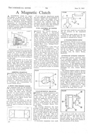
.A MAGNETIC clutch for motor vehicles is shown in patent No. , 772,457. (S. Smith and Sons (England), Ltd., Cricklewood Works, London, N.W.12.) The device works through the compaction of iron-bearing powder when included M a magnetic circuit, and is designed to have a low time-constant so that it responds rapidly to variations in the control current.
The flywheel (1) carries a ferrous ring (2) which is attached to another ferrous member (3). A ferrous ring (4) defines .a pair of annular air-gaps (5 and 6), whilst an energizing winding is disposed within the space (7), current reaching it via slip-rings.
The driven member is in two parts (8 and 9) which lie in the air-gaps, the spaces being tilled with magnetizable powder. When the winding is energized, the powder compacts and torque is transmitted. Such of the constructional .parts as play no part magnetically are made of non-ferrous material.
ASSISTED STARTING
PATENT No. 772,490 gives details of a scheme for assisting the starting of oil engines. -A volatile liquid . is injected into the intake as the engine is cranked. The spray is created by compressed air. (Precombur, Societe pour le Traitement des Combustibles, 14 Avenue Hoche, Paris.) A BODY FOR FROZEN GOODS AN insulated body for the transport of frozen commodities is disclosed in patent No. 772,723. (P. Tapp and R. Tapp, 166 Weir Road, London, S.W.I2.). Its chief feature is that the interior is compartmented, enabling a deep-frozen small load to be carried in the middle of one lightly frozen, thus minimizing heat transfer..
In the plan view shown, it will be seen that a central compartment (1) can be created by closing the doors (2). These lie open in recesses (3) when not required. If not used for deep-frozen goods, the inner chamber can be employed in instances where the weight limit is reached before the bulk. limit, in order to isolate the contents from the remainder of the body and reduce the 'air space around them, thus maintaining their extent of refrigeration.
FUEL CONTROL OF POWER OUTPUT
PATENT Na. 774,170 discloses a scheme whereby a four-stroke engine is fed with an unregulated air supply, carrying fuel the proportion of which is varied to give control. In view of the fact that weak mixtures would not be readily combustible, a separate ignition chamber is provided, fitted with a small fuel-injector and sparking plug. (Daimler-Benz AU., Stuttgart-UntertOrkheim, Germany.)
The drawing shows a plan view of
the cylinder-head arrangements. The inlet valve (1) is located as close as possible to the top-stroke piston position, but the exhaust valve (2) lies in a raised pocket. The ignition chamber (3) feeds this pocket tangentially via the passage 4, and its cap contains an injector-and sparking plug (not shown).
The injector charge is virtually constant, so that the mixture in the ignition chamber is always combustible. When fired, the burning gases are blown out into the main charge and are sufficient to give full ignition in spite of possible leanness.
LOAD-SENSITIVE BRAKIN6 DRAKES are usually designed to give LI maximum retardation when a vehicle is fully laden; this means that in the case of an unloaded heavy vehicle the application may be unnecessarily fierce. Patent No. 773,158 discloses a brake layout in which the action is varied directly by the degree of loading. (Vauxhall Motors Ltd., Luton, Beds.) The drawing illustrates the basic principle of the-scheme. An air reservoir (1) powers the brakes (2) through the usual pedal-operated valve (3). The essence of the scheme is the provision ,of. .a regulator valve (4). This is in series with the air supply and is controlled by the degree of load as determined by the height of the suspension springs (5).
If nneumatic suspension were used, hen the valve would be controlled by he air pressure in the suspension cylinders.
The patent gives details of the construction of the valves both for airoperated or vacuum-servo brakes.
A COATED PISTON RING
PATENT No. 770,22,5 reveals a piston ring provided with a hard-wearing layer for long life, and on top of this a soft layer intended to be worn away during the running-in period. Chromium and tin are said to be suitable metals for the two duties. (Hepworth and Grandage, Ltd., St. John's Works, Bradford.)
AUTOMATIC ENGINE COOLING COOLING systems, especially those of underfloor engines, frequently reduce the engine temperature to a value too low for the engine to give its best performance. A self-regulating system which overcomes this defect forms the subject of patent No. 774,725. (Clayton Dewandre Co. Ltd., Titanic Works, Lincoln.) The scheme employs radiator shutters in conjunction with a clutch in the fan drive, both of which are arranged to be responsive to engine temperature.
In the drawing, 1 is the radiator, 2 the fan, and 3 the clutch in the fan drive. A servomotor (4) operates the radiator shutters, whilst the clutch is energized by the application of air pressure to its casing. The air supply to both units is controlled by a master valve (5). This is responsive to temperature and is inserted in the main water circuit.
The action is such that cool water closes the shutters and stops the fan,
and vice versa. The units may be operated either by air pressure. or by suction, and the patent gives details of the construction of the clutch.


