


Engineer's noteboo
Page 42
Page 43

Page 44
If you've noticed an error in this article please click here to report it so we can fix it.
Things are starting to happen in the area of commercial vehicle transmission development after a long period of inactivity. Tim Blakemore looks closely at what Eaton, one of the leaders in the field, has in store
THE YEAR 1984 will probably be remembered best in transport engineering circles as the year when commercial vehicle transmission development really began to gather pace. Even the most enthusiastic transmission engineer would be bound to admit that this field, at least apparently, had lain fallow for a number of years. Now there are signs of a rich harvest on the way.
Earlier this year Leyland published the results of its work on a continuously variable transmission using a traction variator based on the Perbury Engineering design of the Sixties.
This will be described more fully in a later CM.
Then came news that Scania's computer-aided gearshifting system, which was first described in CM in January 1983, was going into production. One of Scania's reasons for pressing ahead relatively quickly with making CAG an on-line option is that many of its competitors are quite close to having similar systems ready.
ZF has prototypes of a microprocessor-controlled mechanical transmission undergoing on-road trials and may be ready to reveal more at this year's Birmingham Show; DanaSpicer is working along similar lines with Lucas, though completion of this project seems further away; and Renault Vehicules lndustriels at Lyons is developing its relatively new 89 gearbox for microprocessor control.
It would be very surprising if Eaton, since the setting up of the ZF-Spicer International group (CM, May 5) one of the world's two biggest manufacturers of commercial vehicle transmissions, did not have its own ideas about such developments.
Eaton's automated mechanical transmission (AMT) was briefly described at the recent CM/Scania Economy Conference (CM June 30 and July 7). So interesting is that particular gearbox that it warrants a fuller description. But first it is worth looking at the more general objectives of Eaton's development work and at one new gearbox in particular, the Twin Splitter, which will go into production before the AMT.
The synchromesh versus constant mesh debate has been going on for a long time and one of the strongest arguments of the supporters of synchromesh is that gearshifting with this type of transmission is easier. Not that it requires less physical effort, for the shift loads in a synchromesh gearbox are always higher than in an equivalent constant mesh model, but that it requires less skill, because double declutching is not necessary to engage gears cleanly.
Eaton is aiming to counter this argument in the short term with its Twin Splitter by making gearshifting with a constant mesh gearbox virtually as easy as with a synchromesh, without sacrificing any of the constant mesh box's well respected durability.
Looking further ahead, Eaton has an AMT under development which requires no driver effort at all for gearshifting.
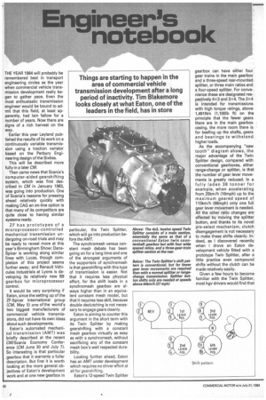
Eaton's 12-speed Twin Splitter
gearbox can have either four gear trains in the main gearbox and a three-speed rear-mounted splitter, or three main ratios and a four-speed splitter. For convenience these are designated respectively 4x3 and 3x4. The 3x4 is intended for transmissions with high torque ratings, above 1,491Nm (1,100lb ft) on the principle that the fewer gears there are in the main gearbox casing, the more room there is for beefing up the shafts, gears and bearings to withstand higher loads.
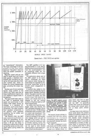
As the accompanying "saw tooth" diagram shows, the major advantage of the Twin Splitter design, compared with conventional gearboxes, either range-change or splitter, is that the number of gear lever movements is greatly reduced. In a fully laden 38 tonner for example, when accelerating from 25km/h (16mph) up to the maximum geared speed of 110km/h (68mph) only one full gear lever movement is needed. All the other ratio changes are effected by moving the splitter button, and thanks to its novel pre-select mechanism, clutch disengagement is not necessary to make these shifts cleanly. Indeed, as I discovered recently when I drove an Eaton development vehicle fitted with a prototype Twin Splitter, after a little practice even compound shifts without the clutch can be made relatively easily.
Given a few hours to become familiar with the Twin Splitter, most hgv drivers would find that they were using the clutch pedal only to move off from rest, changing gear while on the move by adjusting the accelerator pedal position to relieve torque in the transmission.
The front (main) section of the gearbox is virtually the same as the front section of a familiar conventional Fuller twin countershaft gearbox. The splitter (auxiliary) gearing is permanently attached to the output shaft.
To protect the engaging members during splitter shifting and allow a conventional lever gearshift, the splitter requires a blocker. This is one function of the pre-select mechanism. It provides a proper blocking action by means of Gylon-coated sensors located in each of the three mainshaft gears. These sense speed differences between the gears and the jaw clutching members splined to the mainshaft.
Each sensor is also splined to the mainshaft but with enough clearance to allow limited rotation and prevent the blocking teeth on the clutch member from engaging with the gear when speeds are not synchronised.
In a compound shift, from six to seven for example, the splitter button is pre-selected, in this case from position three to one, transmission torque is relieved either by clutch disengagement or accelerator pedal manipula tion and this makes it easy to select neutral. When this occurs the mainshaft speed changes, the sensor unblocks and the auxiliary engages. Then the transmission assumes the characteristics of a constant mesh unit.
Angular ramps on the sensor and blocking teeth of the jaw clutch member make it possible for the mainshaft to change speed and unblock when the front section of the gearbox is in neutral. This also prevents the vehicle's being blocked out of gear when stationary. The only connecting member between the input and output sections of the transmissions is the mainshaft.
The 4 x 3 Twin Splitter is expected to be in production by 1986 with 3 x 4 models following soon afterwards.
The target date for the start of production of Eaton's Automated Mechanical Transmission is some two years later, which gives Eaton's engineers no more than a respectable amount of time to fully develop it. They are well aware of how naturally conservative most hauliers, and indeed manufacturers, are and they are determined to be able to demonstrate the AMT's durability before its introduction.
Even in its prototype form the AMT is an exciting development and it is not surprising that the response from the European vehicle manufacturers to whom it has been demonstrated has been, in the words of an Eaton engineer, "very positive".
As briefly described in CM June 30, the AMT's base transmission is a conventional, twin countershaft, constant mesh, Fuller Roadranger range-change unit; nine-speed in current prototypes, though Eaton is working on a 13-speed version. Indeed one of the attractions of the AMT system, and one of Eaton's longer term objectives, is that it can be adapted to suit almost any gearbox — not just those manufactured by Eaton.
The brain of the system is its electronic control which is of inhouse Eaton design. The design philosophy is for the controller to be provided with sufficient information to determine continuously the status of the driveline. This is then compared with the programmed-in desired status, and control action initiated when necessary. Eaton's engineers have aimed to avoid, as far as possible, control actions based
on "remembered" information. The major advantage in this approach is that any major electronic "disruption" does not leave the system paralysed or recycling.
Magnetic speed pick-ups are used to sense input and output shaft speeds, a standard countershaft gear providing the signal for the input side and a finepitch toothed disc, which replaces the normal speedometer gear, providing the output signal.
Another pair of micro switches signals range position to the control unit. Eaton says that all these modifications require only nine additional tapped holes in the gearbox.
The input shaft brake used on the AMT to decelerate shaft speed and synchronise it with output shaft speed during up changes, is a standard, airoperated, multi-plate Eaton component. The major variation from standard components is the gearbox cover assembly containing the air shifter and valve manifold.
Like Scania's CAG, the AMT uses solenoid-controlled air valves for gearshifting. At present the operating pressure of these is 80 psi, but Eaton is planning to reduce that to 60 psi so that the valves are fully energised before spring brakes are released.
The AMT upshifts in 0.7 sec and downshifts in 1.2 sec. Range shifting occurs concurrently with main box synchronisation and so compound shifts are not noticeably different from single shifts.
The particularly clever part of the AMT system is its clutch control. Prototypes are fitted with ceramic clutch facings because these are regarded by Eaton as the "worst case" as far as smooth clutch engagement is concerned.
A toothed disc added to the clutch cover provides the engine speed signal. Standard flywheel starter ring gears could be used to provide this signal, but that would mean the electronic control unit would have to be adapted to suit the varying number of flywheel teeth on different engine types.
No matter how hard the accelerator pedal was floored, the AMT equipped prototype I drove recently (an Iveco 170.30) always accelerated away smoothly, with no violent cab movement. This is thanks to the "dip piston", one of two air cylinders in the accelerator linkage which are part of the AMT's fuel control. The dip piston limits the maximum rate of throttle opening during the first part of a start from rest and can be used to limit throttle opening when a road speed governor is built into the system. The second, boost cylinder increases fuel delivery when necessary to increase momentarily engine speed, dur
ing downshift double de-clutching for example.
The AMT is designed to provide clutch and throttle modulation for hill starts in the same manner as a skilled driver. In deed, Eaton says that its tests have shown that gradeability with the AMT "is generally greater than could be achieved by a driver with manual operation of these same components."
It is clear that a truly malicious driver could abuse the present system by holding a vehicle on a gradient with clutch slip only, and thereby cause excessive clutch lining wear and/or flywheel damage. Eaton is currently investigating a number of alternative ways of preventing this and it seems certain that it will not be possible on production AMTs.