


New Heavy Type of Cutting-off Machine Tool.
Page 8
Page 9
If you've noticed an error in this article please click here to report it so we can fix it.
The Latest Plant for Dividing Bar up to 8 in. Diameter.
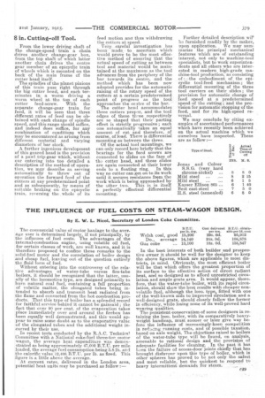
Charles Taylor (Birmingham), Ltd., is a manufacturer of machine tools well known to the productive side of the commercial-vehicle industry. Not only for lathes of all types, but for many specialities which include cutting-off machine tools. The standard Taylor 3 in. inachirie of this kind is to be-found in practically every commercialvehicle factory in this country.
For that reason, if for no other, we recently welcomed an invitation to inspect one of the first of the new and larger models of such machine tools which have been designed to tackle work of this kind on a much heavier scale.
We found one of the new 8 in. Taylor rotary-cutting machines at work on a Government test order when we visited Taylor's factory in Birmingham one day last week, and we were interestedto observe it in operation upon high-grade nickelsteel, cutting of 6 in. ban in 8 in. lengths at a remarkable speed.
The general appearance of this machine is quite well illustrated by two photographs which we reproduce herewith. We have lettered them in such a way as to draw particular attention to certain outstanding mechanical novelties that are embodied.
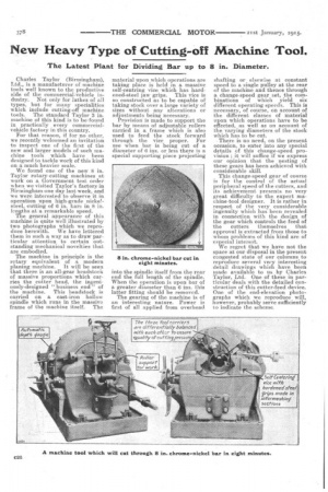
The machine in principle is the rotary equivalent of a modern planing machine. it will be seen that there is an all-gear headstock of massive proportions which carries the cutter head, the ingeniously-designed " business end" of the machine. This headstock is carried on a cast-iron hollow spindle which runs in the massive frame of the machine itself. The material upon which operations are taking place is held in a massive self-centring vice which has hardened-steel jaw grips. This vice is so constructed as to be capable of taking stock over a large variety of sizes without any alterations or adjustments being necessary.
Provision is made to support the bar by means of adjustable rollers carried in a frame which is also used to feed the stock forward through the vice proper. For use when bar is being cut of a diameter of 6 ins. Or less there is a special supporting piece projecting
into the .spindle itself from the rear end the full length of the spindle. When the operation is upon bar of a greater diameter than 6 ins, this latter fitting should be removed.
The gearing of the machine is of an interesting nature, Power is first of all applied from overhead shafting or elsewise at constant speed to a single pulley at the rear of the machine and thence through a change-speed gear set, the combinations of which yield six different operating speeds. This is necessary, of course, on account of the different classes of material upon which operations have to be effected, as well as on amount of the varying diameters of the stock which has to be out.
. There is no need, on the present occasion, to enter into any special details of this change-speed provision ; it will suffice if we express our opinion that the nesting of these gears has been achieved with considerable skill.
This change-speed gear of course is for the control of the actual peripheral speed of the cutters, and its achievement presents n-o very great difficulty to the expert machine-tool designer. it is rather in respect of the very considerable ingenuity which has been revealed in connection with the design of the gear which controls the feed of the cutters themselves that approval is extracted from those to whom problems of this kind are of especial interest.
We regret that we have not the space at our disposal in the present congested state of our columns to reproduce several very interesting detail drawings which have been made available to as by Charles Taylor, Ltd. One of these in particular deals with the detailed construction of this cutter-feed device. One of the end-elevation photographs which we reproduce will, however, probably serve sufficiently to indicate the scheme.
From the lower driving shaft of the change-speed –train a chain drives another change-gear box, from the top shaft of which latter another chain drives the centre gear member of an epicyclic train of wheels which is mounted on the back of the main frame of the cutter head itself.
The spindles of the planet pinions of this train pass right through the big cutter head, and each terminates in a worm driving a worm wheel at the top of each cutter feed-screw. With the separate change-gear train for feed, it will be seen that three different rates of feed can be obtained with each change of spindle speed, and this range should suffice, and indeed does suffice, for any combination of conditions which may be encountered as arising from different material and varying diameters of bar stock.
A further ingenious development of this geared head is the provision of a pawl trip-gear which, without our entering into too detailed a description of the method of operation, we may describe as serving automatically to throw out of operation the forward feed of the cutters at any predetermined point and as subsequently, by means of suitable braking on the epicyclic train, reversing the whole of its feed motion and thus withdrawing the cutters at speed. Very careful investigation has been made. to ascertain which would prove to be the most effective method of ensuring that the actual speed of cutting as between tool and material would be maintained at the maximum as the tool advances from the periphery of the bar towards its centre, and the method which has been now adopted provides for the automatic raising of the rotary speed of the cutters at a certain predetermined point of progress as the tool approaches the centre of the bar. •
The cutter head accommodates three cutters proper, and the tool edges of these t-leee respectiveiy are so shaped that their parting effect is strictly progressive ; each one automatically fakes an equal amount of cut and therefore, of course, of load. There is differential mounting as between the three. Of the actual tool mountings, we can only record here briefly that the bearings for the feed screws are connected to slides on the face of the cutter head, and these elides are again connected at their lower
ends to a floating ring. In this way no cutter can get on to its work until it secures resistance from the work which is being approached by the ether two. This is in itself a perfectly effectual differential mounting.
Further detailed description evil' be furnished readily by the maker, upon application. We may summarize the principal mechanical features which are of outstanding interest, not only to machine-tool specialists, but to work superintendents and all others who are interested in mcdern high-grade machine-tool production, as consisting of :—the embodiment of the epicyclic tool-feed mechanism; the differential mounting of the three tool carriers on their slides; the provision for automatic change of feed speed at a predetermined speed of the etitting i • arid the provision for automatic stopping of the feed, and for its high-speed reversal.
We may conclude by citing examples of ascertained performances which have recently been achieved on the actual machine which we ourselves have inspected. These are as follow
Type of Steel.
4 Actual .0.1 Time of
Cutting c off INS. Si. S.
Jonas and Colver S.S.G. (very hard chrome-nickel) 8 8 0 Mild steel
2 15 Mild steel .. 6 1 5 Kayser Ellison 805 ... 6 1 40
Best cast-steel
7 50 H.S. steel (annealed) 6 80