


A Load-weight Indicator for Lorries
Page 58
If you've noticed an error in this article please click here to report it so we can fix it.
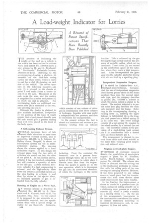
A Resume of Patent Specifications That Have Recently Been Published
THE problem of indicating the weight of the load on a vehicle is one which has been tackled in various ways, and patent No. 440,953 shows a new scheme by H. and G. Newbould, of "Northlands." Redesdale Gardens, Dunston-on-Tyne. Referring to the accompanying drawing, a platform (5) mounted on the hack-axle easing carries the whole outfit, which is eased in and has a dial (3) showing on each side of the vehicle. The device operates in the following manner :—An arm (1) is pivoted to the chassis at point 7 and rocks about a centre on arm 2 on the axle. Movement of the axle rocks the arm, and the motion is magnified by a sector and pinion (4)
to which the dial is attached. For overhanging loads an additional corrector arm (5) is extended to the rear, also pivoting on arm 2.
Although the device is claimed to give accurate indications, irrespective of the position of the load, it would appear that a load placed directly over the axle would give a greater reading than if it were placed in the front of the body space.
A Self-ejecting Exhaust System.
SEVER AL inventors have of late turned their attention to some form of improved exhaust system, and in patent No. 440,955, by J. Johnson, 11, Bullers Green: Morpeth, is shown an auto-ejector system for use in multicylindered engines. The drawing shows the scheme applied to a fourcylindered engine. In this design the exhaust pipes from the two pairs of cylinders are nested one into the other at the point A. In the position shown, cylinder I has just finished exhausting, but still contains a quantity of more or less idle gas. At this moment, however, cylinder 3 is just commencing to exhaust, and the high-velocity blast from this creates a powerful suction on the pipe leading to cylinder 1, and thus, by virtue of the ejector effect, an increased quantity of gas is extracted from the idle cylinder.
Running an Engine on a Navel Fuel.
AN unusual scheme is described in .patent No. 440992 by E. Bientinesi and A. Caproni, both of 27, Via Lucchese, Pisa, Italy. In this patent it is proposed to use ammonia as a combustible material, and the specification deals with a special design of engine for use therewith. Ammonia,
B44 winch consists of one volume of nitrogen in combination with three volumes of hydrogen, liquefies with ease under a comparatively low pressure, and thus is convenient for transportation.
In the present scheme the fuel is stored in a container and receives a preliminary heating from an exhaust jacketing. From the container the ammonia, now in a gaseous form, passes through tubes (2) in the water jacket of the engine, in which place it absorbs more heat from the engine. From the jacket it passes on to the next operation, which is to decompose the gas into its constituent elements, of which the hydrogen is the useful fraction. This is achieved by the gas flowing through heated tubes in the presence of metallic oxides, which act as catalysers. These tubes (1) are located in the combustion space LI the cylinder, where they reach a high tempera ture. After decomposition the gases pass into the cylinder, and after mixing with air are fired by a sparking plug.
Independent Suspension Progress.
IT is stated by Daimler-Benz A.G., 1Stuttgart-Untertiirkheim, Germany, that the use of independent suspension often throws greater stress on the frame members than does the normal rigidaxle type, and the company describes in patent No. 441,048 a scheme in which the above defect is stated to be absent. The method adopted is to permit some free play between the stubaxle 'assembly and the frame. Referring to the accompanying drawing, a rocking lever (I), forming the upper linkage, is ball-jointed (6) to the kingpin, and presses on a helical spring (2) at its inner end. The lower linkage consists of a leaf-spring (3), coupled to the wheel member by a normal eye and pin. The invention consists in the provision of a slack-fitting bush around pia 5 in combination with a slotted joint on shock-damper pin 4.
This arrangement is 'claimed to prevent frame rattle and wheel wobble, at the same time ensuring good suspension and reduced wear.
Progress in Swash-plate Engines.
EVIDENCE of continued research into the possibilities of swash-plate engines is given by W. Hulsebos. Laren, Nord-Holland, Holland, in patent No. 440,545. The scheme described is directed towards solving one of the mechanical problems in connection with the rolling path of the connecting-rod carrying member. Hitherto. it has been proposer] to use rolling cones or bevel gears, but the inventoi: states that with these devices alone small inaccuracies may cause trouble.
In the drawing, the improvement is shown to consist of a pressure hone (3} which, instead of rolling directly on to a stationary cone, presses on a similar member (2) which is freely r-tatable on a bearing sleeve ( I). By the use of this arrangement, inaccuracies in the construction cause sleeve 2 to rotate or remain stationary according to transient circumstances, and, in consequence, it does not suffer.