


Patents Completed.
Page 18
If you've noticed an error in this article please click here to report it so we can fix it.
LOCKING DEVICE.—Harniltun and Stroud.—No. 211, dated February znd, 19o5.—This is a neat form of locking lever, by which the position of any mechanism can be adjusted without operating a detent or the like to release the lever, but after adjustment the operating member is so locked that it cannot be displaced by vibration or pressure put upon the part which it controls. Tfie parts swing about a pin (A) which may be fixed, and concentric with the pin is a fixed easing or shell (Al). Mounted on the pin is an arm (13), for connection to any device requiring adjustment, and on the arm is an eccentric (D). Operating between the eccentric and the fixed casing (Al) are balls (E), normally kept apart by a spring (E). Also mounted on the pia (A) is an operating handle (C) having lugs (C2), which project into the path of the balls (E). With this arrangement it is impossible to move the arm (B) by putting pressure upon its free end, as it
is locked in both directions by the balls .(E), If, however, the handle (C.) is operated, say, to the right, the top lug (Cl) is brought against the upper ball (E) and displaces it, whIlst the bottom lug comes against the arm (II), and this being now freed by the displacement of the upper ball (E), the arm may be moved In the direction indicated by the arrows. If the handle is moved in the opposite direction, the bottem lug displaces the
lower ball (1.:), and the arm (13j uan be inovcd in a counter-cl.iickwiso direction. It will be seen that the moment the handle (C) is released the arm (Ti) is again automatically locked, so that a positive control of the parts operated is obtained, whilst the operating handle is always free and the arm (B) can be immediately moved thereby. Figure 4 shows another form of the apparatus, in which the part (DI is fixed and the eccentric takes the form of a shell (131), integral with the arm (13). The operating handle (C) carries lugs (C2) as before, and its method of operation is the same.
FIRE ENGINE.—Merryweather.—No. r8o5, dated January 3oth, 1905.—To convert steam fire engines that are arranged for horse draught into motor vehicles, the front portions of the side frames are rigidly attached to side frames carrying the motor mechanism by means of plates or brackets. A is a framework on which is arranged an engine (B) and a transmission gear (C) terminating towards the rear in a pair of toothed sprockets (DD). The front portion of the framework is mounted on springs (F) and a steering axle (F). G are angle steel side bars forming part of the framework of the existing steam fire engine from which the fore-carriage has been removed, which carries a boiler (H) and engyie (Ki mounted on wheels (1.)„ to which are attached toothed rings (M) driven by roller chains (N) from the sprockets (D) attached to the framework (A). The framework (A) is attached rigidly to the framework (G) by means of brackets (P), thus converting the two separate portions of framework each mounted on a pair of wheels to one four-wheeled automobile vehicle.
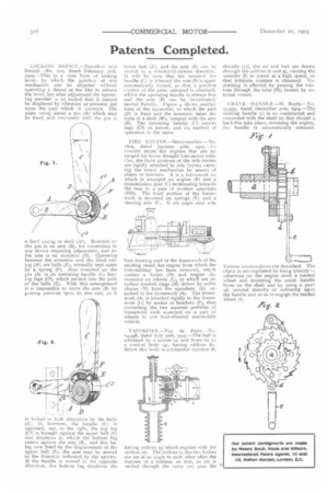
VAPORISER.—Van de Putte.--No. 14,948, dated July 20th, i9o5.—The fuel is admitted by a nozzle (2) and flows on to R. conical body (4), having orifices (6). Below this body is a rotatable member (8) having orifices (9) which register with the orifices (6). The orifices in the two bodies are set at an angle to each other after the manner of a turbine, 80 that, as air is sucked through the valve (to) past the throttle (12), the air and fuel are drawn through the orifices (6 and 9), causing the member (8) to rotate at a high speed, so that intimate mixture is obtained. Vaporising is effected by passing the mixture through the tube (H), heated by external means.
CRANK. IIANDI.E.—H. Bayly.—No. 27,935, dated December list, r9o4.—The starting handle (e) is so constructed and connected with the shaft (a) that should a back-f re take place, reversing the engine, the handle is automatically released.
Various constructions are described. The object is accomplished by fixing directly rr otherwise on the engine shaft a ratchet wheel and mounting tho crank handle loose on the shaft and by using a pawl (d) pivoted directly or indirectly upon the handle and so as to engage the ratchet wheel (b).