


A NOVEL INFINITELY VARIABLE GEAR.
Page 28
If you've noticed an error in this article please click here to report it so we can fix it.
A Résumé of Recently Published Patents.
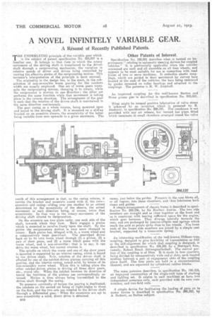
THE IJNDBRLYING:principle of thB.yariable gear which is the subject of patent specification No. 200,337 is a familiar one. It,. belongs to that class in! which the rotary movement of the driving shaft is transferred to the driven shaft through a reciprocating mechanism, the variation in relative speeds of driver. and driven being controlled by varying the effective stroke of the reciprocating Motion. This inventor's interpretation of the principle is most unusual.
The originality in the design lies, in the main, in the substitution of non-reversible worm gearing for, the ratchets whith are usually employed. One set, of worm gears transmits the reciprocating motion, changing it to rotary, while the reciprocator is moving in one 'direction; the other set perfornts the same function while that movement is taking place in the reverse direction. The arrangement of the gear is such that the rotation of the driven abaft is maintained in the same direction continuously. • The gear Casing as a whole rotates, being mounted upon and keyed to the driving shaft. It is mounted on a sliding bracket on an eccentric sheave, the eccentricityof the latter being variable from zero upwards to a given maximum. The result of this arrangement is that, as the casing rotates, it carries the bracket and eccentric round with it, the two_ eccentric and casing—sliding over one another to an extent determined by the eccentricity of the sheave, the actual movement in each direction being, of course, twice that eccentricity. In that way is the rotary; movement of the driving shaft altered to reciprocation.
On the eccentric are two plain racks, one each side of the shaft, towards which they face. Each •engages a pinion which is mounted to revolve freely "upon the shaft.. By the pinion the reciprocatory motion is once more changed to rotary.. Each pinion has, integral with it, a worm wheel and
a comparatively large gearwheel. The gearwyeel drives back on to its own worm wheel through (1) a pinion, (2) a pair of skew gears, and (3) a worm which gears with the worm wheel, and Is non-reversible : that is to say, it can drive the worm wheel, but cannot overrim it-.
The spindle on which the worm and one of the skew gears is mounted is supported by an interior casing, which is keyed to the driven shaft. Now, rotation of the driven shaft is effected by one of the Tatch'et-driven pinions carrying all this gearing, and the interior casing, round solid, by means of its non-reversible worm wheel. While this is taking place the other ratchet-driven pinion is driving all those skew gears, etc., round idly. When the ratchet reverses its direction.of travel the functions of the pinions alas correspondingly reversed. Motion is thus always 'being transmitted to the driven shaft through the casing.
To preserve continuity of torque the gearing is duplicated, the ratchets on the second set being at right-angles to those on the 'first., and the two sets arc coupled to the driven shaft through a differential gear., When the eccentrics are set to zero eccentricity a solid, direct drive is alatained.
B44
Other Patents of Interest. • • "
Specification No 195,091 describes what is termed an improvement "relating to automatic steering devices for coupled vehicles." It is pdrtacularly applicable when the vehicles concerned are each and all steerable on all four wheels, and • appears to be most suitable for use xi connection with road trains of two or more machines. It embodies elastic couplings, which are guided in their movement by curved bars located at the ends of the vehicles, the bars being embraced by guides mounted on roller bearit gs and attached to the couplings. The patentee is H. W. Jonkhoff. • • An improved coupling for the well-fknown Benton and Stone grease gun is described in specification No. 289,381.
• What might be termed positive lubrication of valve stems is achieved by an invention which is patented by E. Akehurst, in specification No. 280,341, The crankcase Is not provided with any air release, but instead has pipes fitted which terminate in small chambers arranged round the valve sterns, just below the guides. Pressure in the case blows oil, or oil vapour, into these chambers, and thus lubricates both stems and guides.
A simple arrangement of chassis frame is described in specification No. 200,236, by Sir Herbert Austin,. The two side members are straight and as close together at the front end as is consistent with leaving sufficient. space for the engine, which goes between. They diverge laterally towards the rear, and are prolonged by quarter-elliptic rear springs which reach the axle at points quite close to the wheels. The front ends of the frame side members are joined by a simple cast bracket, supported by a transverse spring.
An interesting modification of the well-known Oldham-type, coupling, designed to give flexibility of transmission•aa well as the self-alignment for which that coupling is designed, is -described in specification No. 186,591 by a Stuttgart. firm, namely, Robert Bosch Aktiengesellschaft. The central portion of the coupling is of fibre. It is made in four quarters, being divided by comparatively wide radial slots, each located midway between a pair of engagement stets of the, coupling piece itself. The four parts are held in a circumferential. channel, and are separated by cylindrical rubber blocks.
The same patentee describes, in specification No. 1136,318, an imprgyed construction of the single-unit type of starting .and lighting set. It relates to such machines as have two independent armature coils, each provided with its own commutator, and two field coils.
A simple device for facilitating the loading of guns CM to motor lorries is described in specification No. 200,282, by A. Redenti, an Italian subject.