


Patents Completed.
Page 20
If you've noticed an error in this article please click here to report it so we can fix it.
Complete specifications of the following patents will be sent to any address in the United Kingdom by the Sale Branch, Patent Office, Holborn, W.C., upon receipt of eightpence per copy.
An Improved Sleeve-valve.
C. Y. Knight, No. 16,846, dated 19th July, 1912. Cognate application No. 28,694/1912.—This invention relates to engines of the short-sleeve type in which a sleeve travels in the space between the
cylinder and an inwardly projecting head above the piston. The inlet and exhaust ports are sealed by a broad packing ring of eutficient width to cover both of them simultaneously during the compression and explosion strokes. The sleeve iR made no longer than the depth of the head, so that, during its stroke, all parts of it come into contact with the head. The object of this is to improve the cooling of the sleeve by conducting away its heat through the head. This is of particular importance at the inner end of the sleeve owing to the reduction in moss-section of conducting material in the sleeve resulting from the ports formed in it.
Lubricating Worm Wheels.
G. E. Seymour, No. 21,482, dated Oath September, 1912.—This invention relates to means for lubricating spur or worm-gearing of the type described in the British Patent No. 16,762, 1910, in which the teeth are formed of metallic or other laminEe. According to this invention the lubricant is supplied to the working faces of the teeth of the gear wheels by centrifugal force. The accompanying drawing shows a construction of a gear wheel, the teeth of the wheel being formed of laminations held together by a bolt passing right through the width of the teeth and holding the laminations securely between two outside flanges and a central flange which is a portion of the wheel. An annular space is left between the laminations and the rim of the wheel; this space contains the lubricant, and the outside flanges are provided with holes for supplying the lubricating medium to this chamber, screwed plugs being fitted for closing the holes. The lubricant is forced out by centrifugal force through the laminations to the surface of the teeth. It is found that a more silent drive of this gear is obtained by forming saw-cuts around the circumference of the wheel.
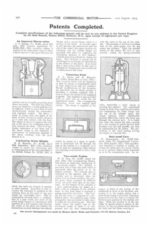
Tempering Steel.
F. 0. Bynoe and H. Edwards, No. 17,014, dated 22nd of July, 1912.— This invention deals with the temperim; of steel by means of superheated steam of high temperature and low pressure. Several modifications of the invention are described, one of which consists in providing a chamber supplied with a rack on which the article to be tempered is placed. The chamber is also provided with an inlet and an outlet for the superheated steam. The accompanying illustration shows this method quite clearly. The steam is supplied to the
article by means of a spray or nozzle, and is afterwards led off through the pipe at the bottom to a condenser, or it can be used for tempering other articles not requiring to be heated to such a high degree.
Two-stroke Engine.
W. H. Tate, No. 15,808, dated 6th July, 1912.—The accompanying illustration shows an improved construction of a two-stroke engine. The cylinder is provided with a fuel inlet port which is uncovered when the piston is in its highest position. The exhaust port is arranged on the opposite side of the cylinder and is uncovered when the piston is at its lowest position, the cylinder ports, being arranged at different levels, are never both open at the same time. At the bottom of the cylinder is a port communicating, by means of a duct, with an extension of the cylinder head ; in this head there is arranged a spring-controlled fuel valve. The seating for this valve is composed of a perforated plate; the. sparking plug, being arranged in close proximity to this valve, is cooled by the incoming gas. The fuel enters below the piston, and on the downward stroke of same it is compressed into the duct communicating with the valve in the top of the cylinder. The pressure of the fuel overcomes that of the valve-spring and the gas enters the cylinder. Upon the upward stroke of the piston the fuel is compressed, closing the spring-controlled valve, meanwhile a fresh charge is entering the cylinder. The compressed charge is fired, thus expelling the piston and compressing the fresh charge into the top of the cylinder again, this charge entering under considerable pressure effectively expels the burnt gas through the exhaust portIt is found that when the engine has been running for a few strokes on petrol the fuel duct becomes very hot and paraffin can then be substituted for the petrol. The perforation in the valve seating serving thoroughly to vaporize tine.
Dust-proof Cars.
NI. Mannesmann, No. 18,997/1912, dated under the International Convention, 22nd August, 1911.---This specification describes a method of totally enclosing the under part of a motor vehicle so as to prevent dust's being deposited on or in the transmission gear. An ex tension is fitted at the bottom of the dashboard in front of the flywheel, connecting it to the engine casing, and a sheet-metal casing is provided, extending backwards from the engine to enclose the fly-wheel and gearbox at the bottom and sides. These are covered in at the top either by special plates as shown in the section, or else by plates fitted between the body and the frame carrying it.