


Increasing Seating Capacity During Rush Hours
Page 36
If you've noticed an error in this article please click here to report it so we can fix it.
A Résumé of Patent Specifications That Have Recently Been Published
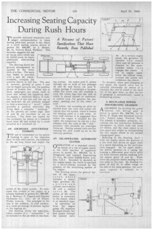
11°provide increased temporary passenger accommodation, in buses during peak-load periods is the object of a novel seating scheme shown in patent No. 559,287, by J. Barker, 24, St. Vincent Road, Wallasey. This inventor suggests the Use'
of tip-up seats which can be folded away to create additional semi-seating capacity.
The drawing shows the genezal arrangement as applied to the lower deck of a bus. The main seat frame is provided with a seat (5), which. normally, occupies the position shown in full line. The seat is, however, pivoted at point 7 and can be tipped upwards into the position shown in broken line. When this is done, passengers can stand, both in front and behind the tipped-up seat. To supply a moderate 'degree of comfort, end 2 of the seat and the top of ihe back-rest (3) are similarly shaped to form a semi-seat or " perch," which provides a position . somewhat less tiring than a complete " stand-up." As the perches are rather high, bars (4 and 6) are provided to act as footrests. The seats are tipped by the conductor by means of a common hand lever (8) and locked by a crank attached to a camshaft (1).
AN AIR-BRAKE ANTI-FREEZE FITMENT
THE use of compressed air for power braking is open to the objection that, in very cold weather, the moisture in the air may freeze and impair the
action of the whole system. To overcome this trouble is the object of a scheme disclosed in patent No, 559,257, by J Rodway, F. Fagard and Clayton Dewandre Co., Ltd., all of Titanic Works, Lincoln. The principle' of the idea is the addition, in Cold Weather. of a small percentage of alcohol vapour to the ingoing air. The drawing shows the apparatus, which consists of a " carburetter " to be included in the air inlet to the brak ing system. Air enters port 3, -passes through one or both of two passages (2 and 4) and leaves via port O. Upper passage 2 constitutes a by-pass, whilst the lower one (4) contains a wick (5) which dips into the well, in which is placed alcohol or methanol. A control cock (1) governs the passages, opening one or the other, or both In action, the incoming air picks up alcohol from the wick and carries the vapour into the system, where it lowers the freezing point to a safe value. In .very cold weather it is suggested that before the engine is stopped for the night, the compressor be run for a few minutes with the cock in the " rich " position; this prevents an overnight freeze-up. During normal cold'-weather running the cock would be set in the mid-way position.
AN OIL-OPERATED AUTOMATIC CLUTCH
OPERATION , of a standard clutch, by means of a rise of engine speed, is the chief function of apparatus shown in patent No. 559,010, by S. Hedgecock and Laystall Engineering Co. Ltd., 53, Great Suffolk Street, London, S.E.I. Intended to declutch at low engine speed, the clutch is operated by a servo-cylinder powered by the pressure of the lubricating system of
the engine.
The drawing shows the general layout of the appa-..
ratus, which includes a centrifugal governor (2), a piston-andcylinder servo-motor (5) and a control valve (6). The piston of the servo motor is connected to the clutch, which is of standard type. In operation, oil from the engine pump (3) traverses its usual circuit, but .first passes through the control valve (6) At a certain engine speed, the governor (2) operates t h e control valve and oil pressure is directed to the servocylinder which then engages the clutch. A fall in engine speed, below the critical value, reverses the action and withdraws the clutch.
To declutch, when gear-changing at any speed, the control valve can be operated electrically by means of 1 solenoid (4): this is wired to the knob (1) of the gear lever, so that the act of grasping it automatically causes a declutching action.
A MULTI-AXLE POWERDISTRIBUTING GEARBOX AGEARBOX for dividing the power between two driving axles is shown in patent No. 558,799, by 0. North, P. Hugh and Scarnmell Lorries Ltd., Tolpits Lane, Watford West: '1 he scheme is in tended, primarily, for vehicles like the well-known Scammell six-wheeler, in which both rear axles are driven, and the chief object is to save space and weight by incorporating the two output shafts in the normal change-speed gear.
Referring to the drawing, shaft 1 from the engine enters the gearbox at a low level and drives an upper shaft at a speed depending on the particular ratio engaged. On the upper shaft— the driven member—is a casing (4) housing a differential gear which .splits the drive between pinions meshing with the output gears (2 and 3). These drive the propeller shafts leading to the two axles at the rear. By hoasing the gears (2 and 3) in offset 'wings on the side of the main gearbox, the extra space required is reduced to a minimum.