


A New Fuel-supply Pump
Page 55
If you've noticed an error in this article please click here to report it so we can fix it.
of clever design
An S.U. Electrical Device that Fulfils the Exacting Requirements Necessary for Use on Commercial Vehicles
TO supply fuel to a carburetter (or an injection pump for a compression-ignition engine) sounds a simple matter, but to obtain perfect reliability under the arduous conditions of use which are the general order of commercial vehicles, is rather more difficult than it would appear. The pump must, of course, be self-priming, be capable of being placed in any position (on the engine, dashboard, etc.), whilst it is essential that a supply of fuel should be available after one or two revolutions of the engine crankshaft and, preferably, that the supply should be available without the engine being turned over at all.
A new supply pump manufactured by the &U. Co., Ltd., Adderley Park, Birmingham, conforms with all these requirements, for it is an electrical device, is self-priming and is capable of delivering under a head of about I lb. per sq. in. and to draw from a depth of 8 ft. or so. The " drain " on the battery is almost negligible as the current consumption amounts to only .4 watt per gallon pumped per hour.
Installation is a simple matter, for the pump can be placed in almost any position where the electrical leads and supply pipes can be coupled up in a convenient manner. The instrument, too, is small, being about 3 ins. in diameter and less than 6 ins. long.
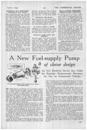
As will be seen from the drawing, a pot-type of electromagnet is used to oscillate a non-metallic diaphragm pump, which causes liquid to be drawn through a non-return valve and to he delivered from the main body, also by a non-return valve. The diaphragm is attached to an armature, a bronze extension of which passes through the magnet pot and abuts a form of make-and-break contact gear at the other end of the magnet pot.
The ingenious feature of the whole design, however, lies in the means adopted for ensuring that the armature and the spindle remain perfectly concentric with the magnet. Just beneath the diaphragm is a recess on the armature in which truncated balls are housed, the outer edges of these sections of " spheres " being retained in a recess in the magnet itself.
As the reciprocating movement of the armature is extremely small, there is sufficient spherical surface on the truncated halls to allow them to work in exactly the same manner as if they were complete spheres, with the result that a rolling action is produced, which is, of course, almost frictionless.
Fuel is drawn into the pump body through a non-return disc valve, when the diaphragm flexes in one direction, and then, on the reversal of the stroke, it is forced out through another non-return 'valve to the carburetter or fuel-injection pump. Inside the main pump body there is an air chamber to allow pulsations to be damped out—an essential feature if needle flutter is to be avoided in the carburetter.
We have observed one of these pumps priming itself when drawing from a depth of 8 ft. and delivering fuel up to about 3 ft. head. This was not the limit, but it is obviously quite sufficient for all practical purposes. Petrol or oil fuels are pumped with almost equal facility, each pump being capable of delivering 8-10 gallons per hour in a normal type of layout.