


AN ELECTRICALLY OPERATED GEAR.
Page 32
If you've noticed an error in this article please click here to report it so we can fix it.
A Résumé of Recently Published Patents.
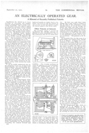
Specification No. 167,413 by J. Cotal describes an interesting and compact epicyclic change-speed-gear which is controlled electrically. The epicyclic gears are altogether embodied within a dished flywheel, and the whole of the control mechanism, including the flywheel, is embodied within a small circular stationary casing. The flywheel itself carries a number of planetary pinion spindles . mounted on ball bearings; one bearing of each spindle is in the flywheel, the other in a cover which is bolted to the latter. The arrangement is such that the whole of the gearing runs in oil.
The driven shaft of the gearing carries a sunwheel which is in engagement with one set of planetary pinions. There amo five sets of these in all, and they are all securely keyed to their spindles so that they all revolve in unison, or not at all.• There are four other sunwheels, each in engagement with one set of planetary pinions and each mounted upon a sleeve which is free to rotate about the driven spindle. Each' sleeve carries at the end opposite to that on which the sunwheel isenounted a flexible disc which carries a rim which actually forms the armature of an eleetro-magnet. There are four electro-magnets, one for each of these discs, all four being carried by the stationary casing which encloses the whole apparatus.
It will be readily understood that by the energizing of any one of these fixed electro-magnets, the corresponding sunwheel is held stationary and in consequence its particular set of planetary pinions is caused to rotate round it, carrying with it the main set of pinions which is in engagement with. the main sun wheel mounted on the. end of the driven shaft. By energizing each electromagnet in turn different ratios of the gears can be obtained. •
There is a fifth electro-magnet which is carried by one of the sleeves upon which a sunwheel is mounted, and close to it is a fifth ring or armature carried by yet another sleeve upon which one of the sun wheels is also mounted. If this particular electro-magnet be energized, two sets of sunwheels of different dimensions are locked together, and the whole mechanism is therefore caused to revolve as one unit, carrying round with it the
. main sunwheel 'on the driven shaft and thus operating as a direct gear.
If no electro-magnet is excited all the sleeves with their sunwheels are free to revolve idly upon the driven shaft and no energy is transmitted. This corresponds to the free engine position or neutral gear. As illustrated by the accompanying drawing, which is reproduced frbm that contained in the patent specification, four forward speeds and one reverse are available. Other arrangements are, of course, permissible within the limits of the invention which, according to the claims of this patentee, consists in electro-mechatical change-speedgear of the type having satellite pinions in groups carried by a flywheel on the driving shaft, the said pinions meshing with a sun gear secured to the driven shaft, and with sun gears adapted to be held against rotation topioduce reduced speed and reversed driving. In this particular construction the electro-magnets controlling the reduced forward and
P.38 • backward speeds are rigidly fixed to the frame, and serve to stop the rotation of one or other of the sun pinions to give the desired speed to the driven shaft.
Other Patents of Interest.
The invention which is covered by specification No. 167,384, although in genious, is rather remarkable for what it has overlooked than for its actual prac ticability. The inventor professes to warm the induction air of an automobile engine, and simultaneously to cool the circulating water, by drawing air through the radiator, 'through a bell mouth, and through a nest of tubes located in the upper portion of the cylinder jacket, finally conducting it to the inlet branch of the carburetter. On the drawing which accompanies the specification, the radiator is provided with a rearwardly projecting tank to which is connected the delivery pipe from the water circulating system. The upper portion of the cylinder jacket affords con siderable depth of water space above the
cylinder head. A series of tubes traverse this space from front to back. At the front end they open into the small end of a funnel, the open large end of which is immediately behind the radia
tor. At their sear ends these tubes emerge into a pipe which is coupled to the air inlet, of the carburetter, which therefore draws all its air through the funnel and tubes and thus warms it. In the engine shown in the diagram, the water circulation is natural or therniosyphonic, and it, does appear that if this construction is to have any real effect on the temperature of the cooling water it will materially interfere with its proper circulation. The patentee is H. H. Justice.
An accessible filter for the sump of a petrol tank is the subject of No. 167,407 by.A. J. Homer. A poppet valve is so mounted in the sump, which is screwed cart° a sleeve mounted in the usual way in the base of -the petrol tank, that when the sump is in place, the valve is open X;tel allows petrol to pass through the sieve in the sump to the delivery pipe.. As the sump is unscrewed however from its sleeve the valve gradually closes and actually shuts entirely before the sump is removed. This allows the latter to be taken away at any time and the sieve cleaned without any loss of petrol.
The change-speed gear, which is the subject of No. 167,372, by G. A. Stafford, is of the constant-mesh type, in .which the two shafts lie side by side in .the box. One of them is a hollow shaft, ?upon which are mounted four loose pinions, any one of which may be keyed to the shaft by means of a 'ball which is caused to project beyond the outside of the shaft by being pressed out to that position by the enlarged end of a spindle' which may be moved longitudinally within the hollow shaft. The engagement of different pinions by this means provides the essential variations.
G. M. Rubury utilizes two of the timing gears of a motorcar engine as the components of a gear pump for transference of the lubricating oil. The claim for novelty appears to lie in the fact that provision is made for supplementary driving wheels to be employed to operate a magneto or other component, without in any way interfering with the efficiency of this oil pump. The number of the specification is 167,333.
The invention which is described in No. 167,381 appears to be more directly applicable to the landing wheels of an aeroplane, although it is.not impossible to conceive of its being useful in connection with a motor vehicle. The hub of the wheel is eccentric to the axle and is free to revolve against a certain amount of frictional resistance when the wheel meets with some imuesual obstruction. In this -way the frame of the aeroplane or car is partly insulated from shocks. The inventor is J. E. Pollak.
In the change-speed gear which is patented by C. G. Redfern in No. 167,362 the heconda7 speeds are obtained by eccentric-driven ratchets and the variations in.-gear ratio are obtainel by altering the throw, of the eccentrics.