


ONE-PEDAL CONTROL A SCHEME in which depressing the - 1-1 . accelerator
Page 90
If you've noticed an error in this article please click here to report it so we can fix it.
pedal also engages the clutch and vice versa is shown in patent No. 872,657. It is intended for smaller types of vehicle in which the clutch springs are relatively light. (R. Hadekcl and J. Herbert, Dumblc Dean, Bourne Lane, Twyford, Hants.)
The drawing shows the scheme in a diagrammatic form, in which 1 is the accelerator pedal, 2 the clutch and 3 the carburetter throttle.
In the position shown, where the clutch is disengaged and the throttle closed, the clutch springs are overpowered by the spring (4) of the pedal which is made strong enough for the purpose.
When the pedal is depressed, the clutch is engaged as the engine speed rises. Both starting and gear-changing are claimed to be made easier by this means. An additional lever, not shown, may be used to put the system out of action to enable the engine to be started when the vehicle is facing downhill.
COMBUSTION HEAD DESIGN PT'HE best shape for a combustion I chamber is hemispherical but this tends to complicate the placing of the valves in the head. An. improved layout claimed to ease this problem is shown in patent No. 875,435. It emanates from Fiat Societa par Azioni. 200 Corso Giovanni Agnelli, Turin, Italy.
R.56 COOLING ROTARY VALVES
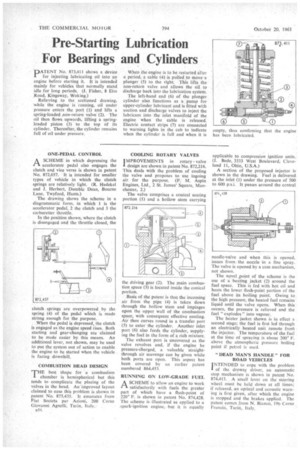
IMPROVEMENTS in rotary valve I design are shown in patent No. 872,216. This deals with the problem of cooling the valve and proposes to use ingoing air, for the purpose. (F. M. Aspin Engines, Ltd., 2 St. James' Square, Manchester, 2.)
The valve comprises a conical seating portion (1) and a hollow stem carrying
he driving gear (2). The main combustion space (3) is located inside the conical portion.
Basis of the patent is that the incoming air from the pipe (4) is taken down through the hollow stem and impinges upon the upper wall of the combustion space, with consequent effective cooling. Air then curves round in a transfer port (5) to enter the cylinder. Another inlet port (6) also feeds the cylinder, supplying the fuel in the form of a rich mixture.
The exhaust port is uncovered as the valve revolves and, if the engine be pressure-charged, a valuable straightthrough air scavenge can be given while both ports are open. This aspect has been covered by an earlier patent numbered 864,453.
RUNNING ON LOW-GRADE FUEL A SCHEME to allow an engine to work
satisfactorily with fuels the greater part of which have a flash-point of 220° F. is shown in patent No. 874,428. The scheme is illustrated as applied to a spark-ignition engine, but it is equally applicable to compression ignition units. (J. Bede, 3333 West Boulevard, Cleveland 11, Ohio, U.S.A.) A section of the proposed injector is shown in the drawing. Fuel is delivered at the inlet (1) under the pressure of 500 to 600 p.s.i. It passes around the central needle-valve and when this is opened, issues from the nozzle in a fine spray. The valve is opened by a cam mechanism, not shown.
The novel _point of the scheme is the use of a heating jacket (2) around the fuel space. This is fed with hot oil and heats the lower flash-point portion of the fuel above its boiling point. Owing to the high pressure, the heated fuel remains liquid until the valve opens. When this occurs, the pressure is relieved and the fuel " explodes " into vapour.
The heater jacket shown is in effect a second stage; the fuel is first led through an electrically heated unit remote froth the injector. The temperature of the fuel at the time of spraying is about 200° F. above the atmospheric pressure boiling point if petrol is used.
"DEAD MAN'S HANDLE" FOR ROAD VEHICLES
INTENDED to cope with the problem I of the drowsy driver, an automatic stop mechanism is shown in patent No. 874,413. A small lever on the steering wheel must be held down at all times; if released, an optical and acoustic warning is first given, after which the engine is stopped and the brakes applied. The patent comes from N. Bianco, 19b Corso Francia, Turin, Italy.