


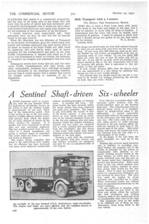
A Sentinel Shaft-driven Six-wheeler
Page 60
If you've noticed an error in this article please click here to report it so we can fix it.
A MOST important point in connec
21. with the new Sentinel 10-12ton shaft-driven six-wheeler, known as the S.D.6, is that the unladen weight is approximately 10 per cent, below that of the chain-driven model. Part of this saving is due to the new boiler, which is a highly efficient vertical watertube pattern, from which the firebox can be easily dropped to expose all the water surfaces for cleaning. It is smaller and more economical in service than any type previously employed. This has resulted mainly from the provision of a double superheater coil giving a uniform degree of superheat. The water tubes arc fewer in number but larger in diameter.
The .engine closely resembles that fitted to the chain-driven D.G. models, but its efficiency has been increased, and many parts lightened considerably
without sacrificing:strength or bearing
areas. At develops 120 b.h.p. Oilgland trouble has been obviated, whilst the steam glands have been improved and made more accessible. The engine is only three-fifths the weight of that of the former pattern. A gear. pump, driven by spur wheels from an extension of the exhaust camshaft, forces oil to the big-ends, gudgeon pins andmain bearings, whilst the cylinder• lubricator. dynamo and tyre pump are combined into a totally enclosed unit gear-driven from the crankshaft ; this also drives a feed pump with double rams which eliminate check-valve chatter and waterhammer in the feed pipes.
Forming a unit -with the Crankcase is the gearbox with spur pinions and dog clutches providing an emergency low gear for useon exceptional hills or soft ground. From this box a propeller shaft with universal joints connects with the double-reduction gear on the forward bogie axle. The reduction-gear drive is through spiral bevels to a layshaft, thence by double-helical gears to the. differential. A .second universally jointed shaft connects•the reduction gear on the first bogie axle with that on the rear, one. The outer ends .of _the live rear axles revolve in roller bearings mounted in the axle casings, whilst the hubs, are secured by large nuts to the tapered ends of the axles. Ball-ended torque rods convey the torque and braking reactions from the rear axles to a cross-member of the frame.
In the design of the rear bogie the same principles are used as on the
Braking has received mach attention and, in addition to providing rearwheel brakes,the company 'can, if the vehicle be intended . for use mainly in exceptionally hilly districts or for quarry working, provide brakes -ore the front wheels ; in either case, there is ample frictional area, and fins cast on the drums assist heat dissipation and prevent tyre deterioration. Each brake drum on the rear wheels contains four wide shoes working together in pairs, thus giving eight brakes for the four wheels. Four of these are coupled together by compensating mechanism and are operated by hand lever. The other four pairs are applied by steam cylinders and controlled by a pedal. When front-wheel brakes are utilized these are operated simultaneously by the steam cylinders.
To give lightness in steering, roller thrust bearings are now fitted to the front axle pivots, whilst the enclosed cab, with windscreen and winding windows, adds to the comfort and gives an exceptionally clear view of the road.
The pneumatic tyres on the model to be exhibited are of 40-in. by 9-in. dimensions, twins being fitted to the rear wheels.