


Practical Points in the
Page 54
Page 55
If you've noticed an error in this article please click here to report it so we can fix it.
PAGEFIELD PLANTAGENET
A New Rigid Six-wheeler with a Gardner Oil Engine, Three Differentials, Adjustable Servo Operation for the Bendix Six-wheel Brakes, Eight Forward Speeds and a Special Engine Mounting AMONGST the concerns which have devoted whole-hearted attention to the possibilities of the oil engine few have specialized to such au extent as Pagefield Commercial Vehicles, Ltd., of Pagefield Works, Wigan. We have already referred to the Pegasus 4-tonner. and to the 6-tonner ; the latter has also' been the subject of a comprehensive road test we have conducted.
We are now able to give the detailed description of the Plantagenet—a rigid six-wheeler for 10-12-ton pay-loads. This model embodies several novel features, one of which—the electric servo —will probably be unique at the forthcoming Commercial Motor Show.
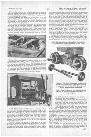
Although this chassis is a new model it is in no souse untried. The Gardner 5L2-type engine needs no introduction to transport men ; it is a proved proposition. The clutch and four-speed gearbox are standard Pagefield features. The working parts of the auxiliary, two-speed gearbox have, for a long period, been embodied in other equally hard-worked units. The Beudix brakes have, for some time, been standardized on this make of vehicle, whilst the Kirkstall three-differential bogie is a popular set of this kind.
Commencing with the frame as a foundation, we find parallel and horizontal main channels with liberal bracing; two tubular members tie together the dumbirons. Behind the gearbox is a full-depth channel-section cross-member and then two tubular members which support the main gearbox. Another one carries the two-speed gearbox. In front of and,behind the bogie are tubular braces, whilst
ROTATING
Line
the pivot for the two inverted semi-elliptic springs of the bogie, and the cross-member which takes the torque—through articulated rods—also serve to stiffen the frame. Finally, another tubular cross-member ties the rear of the frame. ,
A Bishop steering set is mounted right forward and operates through Haworth special joints. Other controls are the gate-type lever for the main gearbox, adjacent to which is the lever for the secondary box, the pedals to the right of these levers and then the hand-brake lever to the dryer's right. The speed control consists of a pedal with Arens mechanism.
For starting, the front two cylinders are decompressed by means of a lever at the front of the chassis and by separate levers on cylinders 8, 4 and 5. The engine-stopping control projects through the bonnet.
Special attention has been paid to the cab; it is free from connections to the radiator and can be removed with little trouble. Engine cowling is rapidly detachable, and the removal of The floorboards of the cab gives easy access to the off side of the power unit.
Four massive but flexible steel plates, of Z-section, attach the engine feet to the frame channels. Spring-loaded bolts permit the required freedom of action, whilst the rear ones have additional torque-resisting stays. The engine is inclined at 5 degrees (to the vertical) towards the near side; this, the maker claims, has a beneficial action in giving smoother running, besides affording more room in the cab.
.13ehind the five-eylindered Gardner engine is a large Ferodo-faced cone clutch, with a stop anchored to the channel-section cross-member. In the four-speed gearbox two points are especially worthy of commendation—the generous proportions of the gearwheels and the provision of a centre bearing for each of the two shafts. Next comes the two-speed box, the proportions of the wheels of which are unusually large; being intended to withstand the heavy torque of the oil engine, particularly at low speeds.
To the rear of this secondary box is a housing which carries a ball bearing supporting the magnet ring of the electric servo ; through the housing passes the driven shaft which has a large flange. On the rear face of the lastnamed is the front Elardy-Spicer joint of the propeller shaft. Coupled to its forward face by eight pins with six-coil springs is the revolving ring of the servo unit. The springs allow the ring to move forwards into contact with the magnet ring, when impelled to do so by the attraction of the stationary magnet.
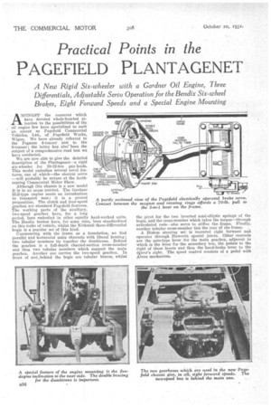
To follow clearly the action of this servo it is best to refer.to the special sketch which we reproduce, studying the following sequence of events. When the driver's foot touches the brake pedal it first depresses a trigger which switches on the current from the battery; this energizes the magnet, pulling the rotating ring towards the stationary magnet. Their maximum degree of contact causes a 70-lb. pull to he imparted, through either steel ribbon to the lever on the frame. The last-named multiplies the pull by three, and passes it on to the brake distribution shaft. It is, therefore, possible to obtain assistance to the extent of 210 lb.; the exact amount can be varied by the turning of a rheostat control on the facia board. This allows, a driver to regulate the braking, according to the load, etc. Further depression of the pedal brings the shoes into contact with the drums, aided by the magnet ring.
Interesting points are that the current consumption is from .7 amp. to 1.3 amp. Should the servo fail, the mechanical operation of the Bendix self-energizing shoes remains unhampered. Three setscrews allow the rotating ring to be adjusted as to its clearance from the magnet ring, thus efficiency can easily be maintained.
Whether the engine be running or not, and irrespective of the direction of rotation of the propeller shaft, equal braking assistance can be employed. This system has had an. extensive trial in service and it offers a truly novel, but essentially practical, solution to the problem of retardation of a 19-ton vehicle.
Ordinary shoes, placed beside the self-energizing ones in the drums of the live axles, are hand controlled. All six wheels carry 40-in. by 8-in. tyres, but larger sizes have been provided for, including the latest big singles.
As regards the power unit, this is the Gardner five-eylindered model, having a maximum output of 62.5 b.h.p. at 1,300 r.p.m. It starts by hand from cold, has forced lubrication, overhead valves and a GardnerBosch fuel pump. The large inspection plates on the crankcase allow the engine to be overhauled without removal from the chassis.
Interesting dimensions are as follow :—Overall length, 27 ft. 6 ins.; pay-load space, 22 ft. l ins.; overall width, 7 ft. 6 ins.; platform height, 3 ft. 111 ins.; turning circle, 60 ft.; wheelbase (to centre of bogie), 16 ft. 111 ins.; bogie wheelbase, 4 ft. 14 in.; track, 5 ft. 9 ins. (rear), 6 ft. 4 ins. (front).
In a nutshell the new Pagefield Plantagenet is a noteworthy newcomer to the large-six-wheeler category and one which, in addition to being original in some respects, is soundly and solidly constructed in every detail.