


A NEW FRENCH COACH CHASSIS.
Page 10
Page 11
If you've noticed an error in this article please click here to report it so we can fix it.
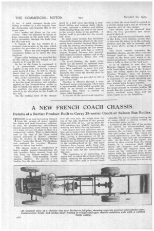
Details of a Berliet Product Built to Cary 25-seater Coach or Saloon Bus Bodies.
TLIERE is en ever-increasing demand from the owners of motor coaches for faster and more luxurious vehicles; in fact, the present-day char-A-banes chassis approaches more closely to that of a large private car than to that of a commercial vehicle. This is particularly true in the case, of the latest coach chassis produced by Messrs. Automobiles M. Berliet, of Richmond Bridge Works, Cambridge Road, Twickenham, and designed for carrying 25-seater coach or saloon bus bodies.
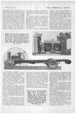
The chassis frame is constructed of heavy section pressed channel-steel, the side members being tapered front and rear from the deepest section in the centre. Seven cross-members ensure absolute rigidity. To provide a low loading line the side members are arched over the rear axle, the height from the top of the side members to the ground being only 2 ft. 4i ins. At the front the side members are slightly inswept, the steering lock being thereby increased.
The engine has four cylinders cast en bloc and provided with detachable heads. The bore is 110 mm. and the stroke 140 mm., giving a horse-power of 30 by RA.C. rating, although the actual brake horse-power developed at 1,500 r.p.m. is in the neighbourhood of 45. The main bearings have bronze shells lined with white metal, similarly constructed bearings being used for the connecting-rod big-ends. •
The crankcase is of aluminium, the upper half, to which the cylinder block is bolted, carrying the crankcase and camshaft. The lower half is divided longi
tudinally, the lowest section forming the oil sump, which is entirely covered by a fine-mesh gauze screen.
Located on the left side of the engine, and driven by helical-toothed gearwheels, is the siugle camshaft which operates the overhead, valves by push rods and rocker arms. The valves are located immediately over the centre of the cylinder bore and are interchangeable. At the front of the engine, and driven by skew gearing from the timing wheels, is a transverse shaft which drives the magneto and centrifugal water pump, te magneto being positioned on the right-hand side of the engine with the make-and-brake facing outwards, whilst the pump is situated at the opposite end of the transverse shaft. Locatetrin the oil sump and driven by
skew gearing from the camshaft is the gearwheel oil pump which delivers oil under pressure to the camshaft bearings, whence it flows through channels cast in the crankcase to the crankshaft main bearings and then by ducts drilled in the crankcase to the big-end bearings. Oil thrown off by the revolving crankshaft serves to lubricate the cylinder vvalls, pistons and gudgeon pins, surplus oil from the main supply pipe to the camshaft -being discharged over the timing gears. Oil is also delivered under pressure to the overhead-valve gear, a channel in the cylinder casting conveying the lubricant to the hollow rocker spindle. Setscrews are provided to regulate the supply to the rocker arms.
Carburation is attended to by a Zenith instrument which is supplied with fuel' from a tank at the rear of the chassis through the intermediary of a vacuum tank mounted on the dash: Located on the right-hand side of the engine is the 12-volt single-unit starterdynamo, which is driven by a silent chain from the crankshaft. A jockey pulley mounted on an eccentric is provided to allow the tension of the driving chain to be adjusted.
The engine is suspended from the main chassis frame at three points, the front of The timing ease being continued forward and tapered and taking its bearing in a trunnion bearing located in the centre of the dropped front cross-member. At the rear the engine is carried by two arms bolted to the chassis side members, the arms being cast integral with the hell-housing surrounding the flywheel.
The drive from the engine is conveyed by a multi-plate dry clutch through a short-drive shaft, having flexible-disc universal joints at each end, to the four-speed-and-reverse gearbox. The clutch is totally enclosed in a housing bolted to the bell-housing surrounding the flywheel. The clutch housing serves also to carry the foot brake and dutch pedals, whilst the centrally positioned change-speed and brake levers are carried on the clutch inspection hole cover.
The gearbox is entirely separate from the engine unit and is suspended from two specially dropped cross-members at • three joints, in the front by a trunnion bearing and at the rear by two arms bolted to the chassis cross-members. Four forward speeds and a reverse are provided, the ratios being as follow :— 1st speed, 30 to 1; 2nd speed, 17.63 to 1; 3rd speed, 10.22 to 1; 4th speed (direct drive), 6.12 to 1.
At the rear of the gearbox and carried on an extension of the second
motion shaft is the transmission-brake drum, ribbed externally for cooling purposes and provided with internally ex panding shoes. In the centre of the drum.and totally enclosed in an oil-tight casing, is the metallic universal joint at the forward end of the open propeller shaft. This universal joint is connected by a pipe to an oil cup mounted on the engine side of the dash. At the rear end the propeller shaft is splined.
The rear axle is of the full-floating double-reduction type, the first reduction being by a bevel pinion and crown w'ieel and the second reduction by spur
gearing. A bevel pinion differential is employed and the whole gearing is mounted on ball bearings, an adjustment being provided for meshing the first reduction bevel gearing. The rear-axle casing itself is a banjo-pattern casting, the hubs of the rear wheels being mounted on ball bearings.
Semi-elliptic springs are fitted front and rear, the latter being underslung and taking all driving and torque strains. The drums for the internalexpanding hand brakes are mounted on the rear hubs, Twin detachable disc wheels, having 955 ram. by 155 ram. pneumatic tyres, are fitted, tyres of the same size also being used on the front wheels. The rear-axle ratio is 6.12 to 1.
The front axle is a substantial I-beam drop forging, with jaw-ended stub axles having inclined pivot pins. The hubs of the wheels are mounted on ball bearings and carry the externally ribbed drums for the internal-expanding frontwheel brakes. These brakes are interconnected with the foot-operated transmission brake.
Worm and full worm-wheel steering is employed, thus providing four wearing surfaces on the worm wheel. The side steering rod is provided with springloaded cups and balls. The cross steering rod is placed behind the front axle and has adjustable jaw-ends connected to the steering arms by pins woring in bronze bushes.
The principal dimensions are as follow :—Overall length, 21 ft 5f ins.; overall width, 7 ft ; dash to end of frame, 17 ft. 1 in.; dash to centre of rear axle, 10 ft. 10 ins. ; track (front), 5 ft. 114 ins. ; track (rear), 5 ft. 1 in. ; wheelbase, 13 ft. 9f ins.; turning circle (approximate diameter), 55 ft.; height of frame from ground, 2 ft. 4-1 The chassis weight is approximately 2 tons, while the gross load which can be carried on the chassis, inclusive of the bodywork, is 31 tons.