


Independent Hydraulic Suspension
Page 68
If you've noticed an error in this article please click here to report it so we can fix it.
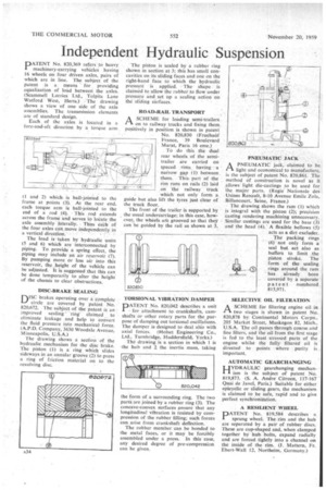
PATENT No. 820,369 refers to heavy machinery-carrying vehicles having 16 wheels on four driven axles, pairs of which are in line. The subject of the patent is a. means for providing equalization of load between the axles. (Scammell Lorries Ltd., Tolpits Lane Watford. West, Herts.) The drawing shows a view of one side of the axle assemblies. The transmission elements are of standard design.
Each, of the axles is located in a fore-and-aft direction by a torque arm
(1 and 2) which is ball-jointed to the frame at points (3). At the rear end, each torque arm is ball-jointed to the grid of a rod (4). This rod extends across the frame 'and serves to locate the axle assembly laterally. Thus earch of the four axles can move independently in a vertical direction. • The load is 'taken by hydraulic units (5 and 6) which are interconnected by piping. To provide a spring effect, the piping may include an air reservoir (7)By pumping more Or Tess air into this reservoir, the height of the vehicle can be adjusted. It is suggested that this can be done temporarily to alter the height of the chassis to clear obstructions.
DISC-BRAKE SEALING
DiSC brakes operating over a complete
circle are covered by patent No. 820;672. The subject of the patent is an improved sealing ring claimed to eliminate leakage and help to convert the fluid pressure into mechanical force. (A.P.D. Company, 3630 Woodale Avenue, Minneapolis. U.S.A.) The drawing shows a section of the hydraulic mechanism for the disc brake. The piston (1) is a ring which slides sideways in an annular groove (2) to press a ring of friction material on to the revolving disc. The piston is sealed by a rubber ring shown in section at 3; this has small concavities on its sliding faces and one on the right-hand face to which the hydraulic pressure is applied. The shape is claimed to allow the rubber to flow under pressure and set up a sealing action on the sliding surfaces.
ROAD-RAIL TRANSPORT
riA SCHEME for loading semi-trailers on to railway trucks and fixing them positively in position is shown in patent No. 820,830 (Fruehauf France, 39 Boulevard
which not only form a guide but also lift the tyres just clear of the truck floor.
The front of the trailer is supported by the usual undercarriage; in this case, however, the wheels ate grooved so that they can be guided by the rail as shown at 3.
TORSIONAL VIBRATION DAMPER
PATENT No. 820,042 describes a unit for attachment to crankshafts, camshafts or other rotary parts for the purpose of damping out torsional oscillations. The damper is designed to deal also with axial forces. (Holset Engineering Co., Ltd., Turnbridge, Huddersfield, Yorks.)
The drawing is a section in which 1 is the hub and 2 the inertia mass, taking the form of a surrounding ring. The two parts arc joined by a rubber ring (3). The concave-convex surfaces ensure that any longitudinal vibration is resisted by compression of the rubber filling; such forces can arise from crankshaft deflection.
The rubber member can he bonded to the metal faces, or it may be forcibly assembled under a press. In this case, any desired degree of pre-compression can be given.
PAA PNEUMATIC' jack, claimed to be light and economical to manufacture, is the subject of patent No. 820,861. Th'e method of construction is novel as it allows light die-castings to be used for the major parts. (Regie Nationale des Usines Renault, 8-10 Avenue Emile Zola, Billancourt, Seine, France.)
The drawing shows the ram (1) which is integral with the piston (2); precision casting rendering machining unnecessary. Similar castings are used for the base (3) and the head (4). A flexible bellows (5) acts as a dirt excluder.
The packing rings (6) not only form a seal but act also as buffers to limit the piston stroke. The form of the sealing rings around the ram has already been covered by a separate patent numbered 815,971,
SELECTIVE OIL FILTRATION
I-1 A SCHEME for filtering engine oil in
two stages is shown in patent No. 820,878 by Continental Motors Corpn., 205 Market Street, Muskegon 82, Mich., U.S.A. The oil passes through coarse and fine filters, and the oil from the first stage is fed to the least stressed parts of the engine whilst the fully filtered oil is directed to points Where purity is important, AUTOMATIC GEARCHANGING
HYDRAULIC gearchanging mechanism is the subject of patent No. 819,873. (S. A. Andre Citroen, 117-167 Quai de Javel, Paris.) Suitable for either epicyclic or sliding gears the mechanism is claimed to be safe, rapid and to give perfect synchronization.
A RESILIENT WHEEL ATENT No_ 819,584 describes a sprung wheel. The rim and the hub are separated by a pair of rubber discs. These are cup-shaped and, when clamped together by hub bolts, expand radially and are forced tightly into a channel on the inside of the rim. (J. Mattern, Fr. Ebert-Wall 12, Northeim, .Germany.)