


A Hydraulic Brake with Safety. Devices
Page 58
If you've noticed an error in this article please click here to report it so we can fix it.
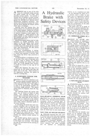
A SERIOUS leak in one of the pipe 11 lines of a hydraulic brake can put the whole system out of order, with possibly serious results. To provide a second line of defence in these circumstances is the aim of a device shown in patent No. 697,509, by F. Korber, 85-97 Zeithstrasse, Seigburg, Germany. The patent also discloses a means for warning the driver should the master piston Show signs of leakage.
Dealing with this feature first, the master piston (1) is Worked by the pedal in the usual manner. Inside the cylinder is a second 'piston (2) which normally. is inactive because a hole passes cen• (rally through it. Fluid moved by the• Master_ piston is thus enabled toreach the multiple exit ports, one of which is shown generally at 3.
• Should.. the niaster piston start to leak, however, it would gradually Move nearer to the idle piston until actual contact was made. When this occurs, a conical nose (4) closes off the central hare, and _thenceforth the idle piston
does duty as the master. _
In these circumstances, a springloaded catch(5) is released; this closes a switch -andoperates a tell-tale light that warns the driver that attention is
ITere4arY,
TO guard against a breakdown of one of the pipe lines, each of the four exits is fitted with a piston (-6). During normal braking,' the piston rises very little, but if the leakage were serious, it would be forced to the topof its
cylinder. • When • this happens, the face (7) is sealed off by the piston and thus the' faulty line is cut out. Once forced to the uppermost position, the piston is held by a spring clip.
A SUSPENSION SYSTEM FOR . TRAILERS ;
D ATENT No. 695,535, discloses a sus
pension system intended mainly for . large multi-wheeled trailers, although it is not limited to this use. The scheme is said to be particularly suitable_ for traversing rough ground. The patent comes from K. Nystrom, Fack 20, Teg, Sweden.
The drawing shows the spring unit used, one of which is fitted to each wheel. The cranked portion (l). is formed into a stub-axle and carries the wheel. The inner part of the crank is journalled in a bush (2) in the tubular housing, and is further guided by an inner bush, whichis fastened rigidly to the outer housing.
A coil-spring (4) forma the main suspension member; this is fixed at one end to a collar (5) on the spindle and at the other to the inner bearing bush. The latter member is carried by an inner sleeve (6) which can be "wound up" before being fixed by screws. This enables any desired initial tension to be given.
The smaller spring, shown inside the other, deals with rebound, winding up as the larger one unwinds, This spring can also be pre-tensioned by turning its anchor disc, s40 BALL-BEARING STEERING GEAR
D ATENT No. 697,706, from Daimler" Benz A.G., Stuttgart-Unterturkheim, Germany, shows a steering gear in which the worm thread is provided with balls between it and its put. The chief novelty is that instead of the thread being filled with one long row of balls, two separate groups in series are used, each of which has its own return duct.
NEW TYPE OF ROLLER BEARING
AROLLER bearing that will withstand both radial and axial loading, forms the subject of patent No. 697,153 (A. B. Svenska Kullagerfabriken, 17 Artillergatan, Goteborg, Sweden). In addition to being used in the normal rotary manner, the same principle can be applied to straight-line
motion, as in a machine-tool slid In the drawing the races are s in section with a roller in pos Each race is V-grooved as showr the rollers are alternately placed their axes at 90 degrees to each The roller shown in the drawing on faces 1 and 2, whilst those on side of it would bear on the °the] faces of the V-groove.
• -Therace (3) is made in piece, ut to permit assembly the one (4) is formed as two separate The cage is provided with tongues which can be bent either to suit the two plane's of the 4-allei
AN IMPROVED .FORM OF } SPOT
DATENT No. 697,3018 refer!
improvements in induction folds; and conies fromG. :Ailda Queens Road, .Weybriclge, Si The design shown is suitable for cylindered engine, and the basis .o Patent is the way in which a hot-si heated by the exhaust gases. , The drawing shows the manifo a vertical half-section. It is ma' two parts, an *upper meniber for the exhaust conduit,with the inlet forming the lower haIi.1*The 'two are united by a series . of screw ISIidWaY in the induction pipe i orifice (2) to, which. the earburen attached, and opposite this is a se orifice (3). * The latter is closed by a thin s metal cone (4) Which is directly ii path of _the incoming mixture. exhaust face of* the cone is fed pair of small conduits which collec exhaust gases from two of the cyl outlets and direct them on to the The main exhaust chamber ma: water cooled, and a jacket (5) ma provided for this purpose.
A NON-FOULING SPARKIN PLUG
A SPARKING plug, for which
virtues are claimed, is show patent No. 697,258 (Boeing Air] Company, Seattle, Washington, U.: It is said to be free from bumin the electrodes, will not oil-ur become shorted by carbon, and reduce detonation.
The drawing shows a section o: plug; it is generally of normal di except for the addition of a nosel (1). This has a venturi-shaped and forms an ante-chamber in w the electrodes are housed. The portions of the bores are not ail in the example shown the small
can be Ain. to in. diameter, w the large end may be between -7-6 in, Ain. diameter.
The plug may be initially mad shown, or an ordinary plug ma! fitted with an adaptor containing ante-chamber. An— additional v claimed is that a much leaner mi) can be used without misfiring, reason being that the plug shoo tongue of flame out of the chamber thus provides for better ignition 01 charge.